Another weird idea that I got while musing.
I was thinking about the difference in output Z of the two sections of cathodyne when a strange thought occurred to me. Could we use only the follower side as output (for low Z) and use the plate signal for negative feedback for response shaping.
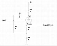
Visualize a standard cathodyne but instead of taking the plate signal to a power tube connect it via a capacitor to the grid. and take the signal from the cathode resistor to feed the following circuitry. So we could define one pole using the feedback path and then use the low Z of the CF to feed additional passive eq.
Could it be done? Would it work as outlined? Is there any advantage of such an arrangement over other more conventional approaches?
mike
I was thinking about the difference in output Z of the two sections of cathodyne when a strange thought occurred to me. Could we use only the follower side as output (for low Z) and use the plate signal for negative feedback for response shaping.
Visualize a standard cathodyne but instead of taking the plate signal to a power tube connect it via a capacitor to the grid. and take the signal from the cathode resistor to feed the following circuitry. So we could define one pole using the feedback path and then use the low Z of the CF to feed additional passive eq.
Could it be done? Would it work as outlined? Is there any advantage of such an arrangement over other more conventional approaches?
mike
Except that the tube already has 100% feedback and the source impedance of whatever is driving that grid shunts whatever it's getting from the plate. I'd have to work out the equations to be sure, but I think all you'll have is a cathode follower with a lousy input impedance.
Probably not what was originally intended, but how about using a cathode follower to drive the output tube grid and the plate feedback from the output tube comes back to the cathode follower's plate.
That way the CF tube provides 1/Mu feedback attenuation approximately.
Don
That way the CF tube provides 1/Mu feedback attenuation approximately.
Don
mashaffer said:I was thinking about the difference in output Z of the two sections of cathodyne mike [/B]
If you assume that each side is driven one at the time you are right, but..........................when driving a PP-load you are wrong as both sides have about equal(and very low) Zout. Well below 3kohm/side for a 12AX7 with 1,5mA Ia. On the downside is that a high B+ is needed to get full swing.
Putting a frequency selective network in the feedback will cause the input impedance to vary with frequency, besides its effects on the CF stage gain. You may get more poles in the frequency response than you expect. I would simulate any design like this (including the previous driving stage) to check the results.
Don
Don
- Status
- This old topic is closed. If you want to reopen this topic, contact a moderator using the "Report Post" button.
- Home
- Amplifiers
- Tubes / Valves
- Cathodyne follower? :)