Oneday I will want to build a "classic" tube amp. The Mullard schematic posted here, is using the el84 in pentode right?
So I suppose I could ask for a UL tap as well when getting the output transformer wound? Then I could add a switch so I can switch between UL and triode mode.
When disconnecting the ul tab with a switch how should I wire the screen? I am still confused about triode or pentode mode. When I pseude triode mode I should just connect the screen to the anode via a small resistor?
[EDIT]As opposed to a pentode that has a seperate b+ connection?[END EDIT]
Thanks in advance.
Attachments
A LA MODE.
Hi,
Yes, the EL84 is run in penthode mode.
You could ask for an UL OPT, no obligation in actually using it though.
You could ground the screen or tie it to the cathode.
No, that is regular penthode mode.
Pseudo triode just means that you try to convert a penthode into a triode...since it is not a triode from the start they call it a pseudo-triode.
Confusing, isn't it.
Cheers,")
Hi,
Yes, the EL84 is run in penthode mode.
You could ask for an UL OPT, no obligation in actually using it though.
When disconnecting the ul tab with a switch how should I wire the screen?
You could ground the screen or tie it to the cathode.
When I pseude triode mode I should just connect the screen to the anode via a small resistor?
No, that is regular penthode mode.
Pseudo triode just means that you try to convert a penthode into a triode...since it is not a triode from the start they call it a pseudo-triode.
Confusing, isn't it.
Cheers,
Yup,
The circuit using the EL84 is the original, the only variations I've come across remove the bass control from the feedback circuit and the top-cut treble from the input, and replace them with the passive bass/treble controls often seen with the 5-10 amp.
Because of the direct coupling between the EF86 and the EL84 I'd be very careful about possibly upsetting circuit conditions by converting the EL84 to triode operation. You could convert the coupling to traditional RC, but then you would risk greater distortion and less bass response. The 3-3 used direct coupling in an attempt to overcome these limitations in a small amp.
If I remember rightly even in the 60s the 3-3 came in for criticism, many purists felt that using grid bias on the EF86 rather than cathode bias could result in increased distortion.
Bas, using a resistor is still "triode mode". The decware amp, among hundreds of others use the resistor to limit current flow surges - thus protecting the screen grid. In class A designs, they are not really needed.
So, in your amp, either the screen will be connected to the UL tap, or directly to the plate.
In no case would you ground it - I'm not sure why Frank suggested that. He is thinking of the "suppressor grid", G3, maybe? This is tied to the cathode internally.
So, in your amp, either the screen will be connected to the UL tap, or directly to the plate.
In no case would you ground it - I'm not sure why Frank suggested that. He is thinking of the "suppressor grid", G3, maybe? This is tied to the cathode internally.
Thanks for the background on the Mullard!
I do not like the feedback etc...or the top cut treble, etc.. so I might just not include that..on the other hand that defeats the object a little ......as I wanted to build something verbatim..
but then I got doubts again and thought fr instance about the UL tap.
Maybe I should just build it stock first and then modify ...could be an interesting educational experience.
He is thinking of the "suppressor grid", G3, maybe? This is tied to the cathode internally.
Must be.
t..been thinking about that too...
Why do they always show that as a wire? When it is allready internally connected? Maybe because some were and some were'nt.?
Bas,
You've got it right - in some valves g3 was internally connected (like the EL84) and some it wasn't (lie the EF86).
I agree with you on the bass control in the negative feedback circuit - one of the advantages of using direct coupling in the 3-3 was that with less phase shift greater amounts of feedback could be used to improve linearity. By having a frequency selective system to reduce feedback at lower frequencies (allowing greater gain at low frequencies) it will therefore also allow more distortion at low frequencies, because of the lower feedback!
TRIODE MODE.
Hi,
Isn't pseudo-triode mode operation achieved by connecting the grids together?
Which in this case will tie the grids to the cathode of the 6BQ5...
I could be wrong about this , but tieing the g2 to the anode doesn't turn the tube into a triode IMO.
Cheers,
Hi,
In no case would you ground it - I'm not sure why Frank suggested that. He is thinking of the "suppressor grid", G3, maybe? This is tied to the cathode internally.
Isn't pseudo-triode mode operation achieved by connecting the grids together?
Which in this case will tie the grids to the cathode of the 6BQ5...
I could be wrong about this , but tieing the g2 to the anode doesn't turn the tube into a triode IMO.
Cheers,
Re: TRIODE MODE.
Yes, you are wrong about that. It does turn it into a triode. A "pseudo triode" in fact. That is how you make one.
UL was also called "super triode" mode occasionally, back in the day.
fdegrove said:I could be wrong about this, but tieing the g2 to the anode doesn't turn the tube into a triode IMO.
Yes, you are wrong about that. It does turn it into a triode. A "pseudo triode" in fact. That is how you make one.
UL was also called "super triode" mode occasionally, back in the day.
PENTHODES.
Hi,
Thanks Joel, I was starting to realise it.
As you can see I obviously don't look at penthodes often enough.
Cheers,
Hi,
Yes, you are wrong about that. It does turn it into a triode. A "pseudo triode" in fact. That is how you make one.
Thanks Joel, I was starting to realise it.
As you can see I obviously don't look at penthodes often enough.
Cheers,
Triode vs Pentode
Bas,
I asked about this some time ago and I still don't see any difference in the wiring between triode and pentode with the 6bq5 (internally connected suppressor).
It looks to me like the screen is connected to the + side in both modes (using a resistor).
Is there really a wiring difference between the two modes?
Still confused on this,
Rick
Suppressor
It doesn't matter where the suppressor is connected. It has a coarse pitch, and electrons with any reasonable energy fly through the gaps. It's only there to repel the low energy ones from the anode in pentode mode. The valve would work ok without it, just with a kink in it's characteristic.
It's the screen grid (G2) that's the important one:
If it is connected to a supply, it determines the pentode charcteristics of the valve.
If connected to the anode, it becomes part of the anode. This is a psudo-triode.
If a resistor is fitted in series with G2 to the anode, things become more complicated. Voltage is dropped across the resistor, and the G2 and anode voltages will differ. The valve will be neither triode or pentode.
If G2 is connected to a tap on the output transformer, it's still a pentode, but the feedback to G2 tends to improve performance. Some say it acts more like a triode.
Confused? I hope not
Hi Rick,
I think I have finally got it now
The difference is small...instead of being connected to b+ after it has been decoupled with an extra resistor and cap = PENTODE
OR
wired directly to or with a resistor to the anode without any other decoupling = TRIODE
Hope this is right
I think I have finally got it now
The difference is small...instead of being connected to b+ after it has been decoupled with an extra resistor and cap = PENTODE
OR
wired directly to or with a resistor to the anode without any other decoupling = TRIODE
Hope this is right
Bas and John,
Bas--I don't see the cap that decouples--so, still not getting that part.
John--
Doesn't tying the screen to the anode or supply result in essentially the same thing--positive wrt to cathode and current flow? (Voltage drop across tranny is not significant? )If so, then how is pentode mode different from psuedo triode?
Rick
fragman56 said:Doesn't tying the screen to the anode or supply result in essentially the same thing--positive wrt to cathode and current flow? (Voltage drop across tranny is not significant? )If so, then how is pentode mode different from psuedo triode?
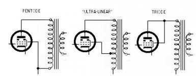
It is VERY different, because when the screen is tied to the "bottom" of the output transformer, it is seeing none of the signal voltage from the plate circuit, since this develops across the output transformer primary winding. If we move the tie point further up - to say 40% of the winding, then we have ultra-linear. The screen grid is now "seeing" 40% of the signal from the plate circuit. Move it all the way up, so it is connected directly to the plate and it is now seeing 100% of the plate signal. It now IS the plate! That's why we say it's now in "triode mode".
Now do we get it?
...life is simple - valves aren't...
There are some problems with psuedo-triode mode that are not huge but benefit from some attention.
1) it is possible for the direct connection of screen grid 2 to the anode to induce high frequency parasitic oscillation. One cure for this is the low value resistor in this connection either between sg2 and anode or at the anode( in stopper mode) with the sg2 connection made to the b+ side of the resistor. Of course this introduces some feedback into the equation but it is usually regard as trivial.
2) with sg2 and the anode at the same potential and sg2 seeing the electron flow first, sg2 has a tendency to act as the anode itself and hence a relatively high current can flow through sg2 shortening its life. This can be overcome by introducing a small voltage offset between the anode and sg2, bypassed by the signal. Typically 30Volts is an effective voltage offset that causes almost all the current to flow through to the plate. The 30 volts can be easily obtained by as zenar diode string of six 5V6 zenars as these have almost zero temperture coefficent and almost zero noise. Bypass these with a high value 'cerafine' capacitor or it's ilk and the triode usually sounds better than without the offset.
ciao
James
- Status
- This old topic is closed. If you want to reopen this topic, contact a moderator using the "Report Post" button.
- Home
- Amplifiers
- Tubes / Valves
- Mullard 3-3