I was thinking about modifying a project that's on a PCB. I'd like to use panel mount tube sockets, and keep the wires as short as possible. I'd also like to be able to service this PCB in the future w/out desoldering all of the tube wires.
My thought was to leave the sockets on the PCB, and use a sort of tube plug to plug into the PCB mounted sockets, and then the other end of the "plugs" would have wires going up to the panel mounted sockets. That way I can keep the wires short and just unplug the tube extensions when I need to service it.
Is there such a thing? I noticed for the larger tubes, I can get tube bases, which might work, but I haven't found anything that will work for the 9 pin tubes.
thanks
http://cgi.ebay.com/Vacuum-Tube-Soc...ryZ73375QQssPageNameZWDVWQQrdZ1QQcmdZViewItem
You could probably get some socket savers to do the trick.
You could probably get some socket savers to do the trick.
Two more sets of contacts for signal and everything else to go through, probably not the best thought for long term reliability, HF stability or sound.
How about cutting clearance sized holes in the top of the chassis and plugging the tubes directly into the pcb. They'll be slightly recessed, but this is not an unusual solution. You would have to be extra careful locating the socket centers so that all of the holes line up properly, and you'd have to mount the board solidly so it does not flex a lot upon tube insertion or removal.
How about cutting clearance sized holes in the top of the chassis and plugging the tubes directly into the pcb. They'll be slightly recessed, but this is not an unusual solution. You would have to be extra careful locating the socket centers so that all of the holes line up properly, and you'd have to mount the board solidly so it does not flex a lot upon tube insertion or removal.
Kevin, I know..... Thats the problem. But the reason I want to mount the sockets externally is for looks. And because all of the wiring is on the PCB, I was going to use a wood panel.
The thick wood panel is why I need to go top mount. I suppose I could route the holes out at an angle, and use bottom mount sockets. Then I can unscrew the sockets from the wood panel, and just lift the panel right off the top if I need to service it.
That might be the best idea.. bottom mount sockets and solder wires from them directly into the pcb.
You guys think you have it rough w/ the spouse approval factor.... It's MUCH worse when your wife is an architect. The design.. style.. looks are 15x more important than anything else.
"You're not putting that thing next to my $11,000.00 1929 Mies van der Rohe sofa!! Are you out of your mind??"
and dirty shoes or dog hair... forget about it!
Hi wicked1, I can certainly understand the concern when the hifi is sharing a room with any Mies van der Rohe piece. 
I needed more isolation from our main living space and when my spouse to be (we've been married for a while now) proposed giving me half the basement for my hobby and doing a lot of work to make it hospitable I was quite quick to agree. As discussed elsewhere it is my "man cave" - given my taste in music (which doesn't always parallel my wife's) it is a good thing I have a separate place to listen.
She has been encouraging me for years to install wiring between the living room and basement listening room so that we can run some speakers there during parties.. Eventually I will get around to it. The Tangband back loaded horn kits look appealing..
Lately aesthetics have started to become important to me too, and while I am boringly middle of the road, I have tried to make my tube amps look like something other than the proto-types they usually are.
Do post a picture of your amplifier when completed, I'd love to see it.
It's definitely not all bad. Just like you were saying, she's forced me to care about the finished product, rather than stopping as soon as it works. It's caused me to make some very professional looking projects.
Ive given up on my downstairs cave... I've got a network consulting business, and countless ADD-like 1/2 finished projects down there. They'll get finished when I stop getting distracted by better projects. But basically, the basement is beyond hope now. It's turned from a den into a workshop.
And for those who read my last message and must think we're completely insane, I should mention that I was exaggerating on the cost of the sofa.. but it did cost more than anyone should spend on something you sit on. I guess it's no different than me and my comptuers, tho.
Ive given up on my downstairs cave... I've got a network consulting business, and countless ADD-like 1/2 finished projects down there. They'll get finished when I stop getting distracted by better projects
. But basically, the basement is beyond hope now. It's turned from a den into a workshop.And for those who read my last message and must think we're completely insane, I should mention that I was exaggerating on the cost of the sofa.. but it did cost more than anyone should spend on something you sit on
. I guess it's no different than me and my comptuers, tho.Hi wicked1,
My workshop and listening space are combined, but at least it is electronics only, the wood shop is next door, along with our washer/drier and fab new steam boiler which sounds just like a large kettle about to boil when it is heating the house ...
I've finally managed to finish most of those perpetually lingering unfinished projects or decided to get rid of the ones I know I'll never get to. The result is somewhat less clutter, but I've got at least a new line stage and an 845SE amplifier up my sleeves for the next couple of acts.. Never ending.
She sometimes asks me how many amplifiers I actually need, and I tell her none beyond the one I am currently using, while qualifying that comment that what I want is an entirely different matter.. The pleasure of designing and building something is an end in itself, and a healthy outlet. (Though perhaps not for the wallet..)
cwujek said:http://cgi.ebay.com/Vacuum-Tube-Soc...ryZ73375QQssPageNameZWDVWQQrdZ1QQcmdZViewItem
You could probably get some socket savers to do the trick.
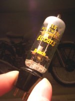
Better stay away from this chinese stuff, it is not very well build.
My intension with these was to try tubes with unusual pin-outs.
When I plugged in the first tube the glas near the pins broke.
Attachments
It is possible to mount the tube sockets above the PC board an inch or two. The first time I did this I just used some solid 14 gauge copper wire soldered to each socket pin to make extensions. Use these wire extensions for all pins except the grids. I used 100 ohm resistors for the grid extensions. These were in addition to the grid stoppers on the PC board.
I got some thin brass tubing at a local hobby shop which will just slip over the pins on the tube sockets with a little persuasion and fit through the holes in the PC board. I plan to use this for my next "double decker" amp design.
I got some thin brass tubing at a local hobby shop which will just slip over the pins on the tube sockets with a little persuasion and fit through the holes in the PC board. I plan to use this for my next "double decker" amp design.
tubelab.com said:It is possible to mount the tube sockets above the PC board an inch or two. The first time I did this I just used some solid 14 gauge copper wire soldered to each socket pin to make extensions. Use these wire extensions for all pins except the grids. I used 100 ohm resistors for the grid extensions. These were in addition to the grid stoppers on the PC board.
I got some thin brass tubing at a local hobby shop which will just slip over the pins on the tube sockets with a little persuasion and fit through the holes in the PC board. I plan to use this for my next "double decker" amp design.
I LIKE this idea a lot - good tip George!
KaDe said:
Better stay away from this chinese stuff, it is not very well build.
My intension with these was to try tubes with unusual pin-outs.
When I plugged in the first tube the glas near the pins broke.
Bummer, apparently rare tube as well. I've had this happen with some Tungsram and EI tubes in the past with a variety of different western made sockets which were all of good to exceptionally good quality. These tubes just had very thin glass, and possibly a very slight pin misalignment which upon insertion caused the tube base to crack - tried that thing with any other tubes?
Encouraged by your interest Kevin,
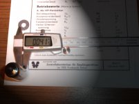
I plugged a chinese 12AU7 into this thing today. This fits in more easy, with less pressure and did survive the insertion.
I always had the impression about the chinese tubes to go into the socket more easy
and checking the pin-diameter it proved to be rather thin with .o385"".
These stingy chinese guys save raw material wherever they can.
The cracked ECC813 was a pre production labatory sample (otherwise similar to 6463) and did measure .o415"" at the pins.
Attachments
I got some thin brass tubing at a local hobby shop which will just slip over the pins on the tube sockets with a little persuasion and fit through the holes in the PC board. I plan to use this for my next "double decker" amp design.
I have been perfecting this technique to allow mounting a TubelabSE PC board about an inch and a half below the deck but place the tube sockets on the chassis deck.
I now have copper (or brass) tubing in two diameters for each socket. I use a short piece of the larger diameter as the "splice" between the socket pin and a longer piece of the smaller diameter tubing which is nearly the same diameter of the socket pin and passes easilly through the PCB.
For 9 pin sockets the small tubing is 1/16 inch (.062) and the larger tubing is 3/32 inch (.093).
For 8 pin sockets I am using .093 and .125 inch tubing.
I just soldered some 3/16 inch tubing into the PCB and soldered the 300B sockets directly to the tubing. I will post pictures of this procedure on my web site, and here if anyone is interested the next time I make some.
Does anyone have pics of this technique?
- Status
- This old topic is closed. If you want to reopen this topic, contact a moderator using the "Report Post" button.
- Home
- Amplifiers
- Tubes / Valves
- extend tube sockets, or tube "plugs"?