Hilarious. Finally something that may outdo the hugeness of my class A PP triode 813 design that was the size of a 3 drawer filing cabinet/channel and weighed 90kg ea. The sort of OTT PSU and LCLC filament supplies were the main reason for the weight.G.Kleinschmidt said:
Attached below are a few crappy conceptual drawings of how I’m going to construct this amp. (No dimensions added yet and the scribbles are not really to scale, but they should give an idea.)
The amp will stand upright, like a tower, probably 1 to 1.5m tall. It will be constructed around a TIG welded frame made from 50mm by 50mm aluminium angle 5mm thick. This frame will support everything, including the transformers.
I'm gonna watch this project with interest.
There is a higher power and higher bandwidth alternative. Though shipped to AU Im sure its a pretty penny.
400W toroidal OPT. Supports 8 KT88.
They had some non potted versions of these on their surplus page, but they are now gone. I got a pair and these are the ones that I am using. The transformers were $138 USD each plus $65 shipping, DEAL!
GKlein# spare a thought.
One of the biggest hiccups with the big game amps with crowded top chassis is ventilation. If one keeps to the 4" valve-holder centre to centre convention (as per KT88 GEC recommend) then for long term reliability a holed top chassis will keep it around 25°C above ambient without a fan. That is already stewing. This issue has been in another thread.
I learn't early on to keep electrolytics in coolest places low down and tubes in upper places. Obviously if you throw-in a fan then there is added noise.
6 x KT88 creates enough heat to simmer an egg and if you are having regulator tubes thrown in, you can cut down the room thermostat.
richj
richwalters said:GKlein# spare a thought.
One of the biggest hiccups with the big game amps with crowded top chassis is ventilation. If one keeps to the 4" valve-holder centre to centre convention (as per KT88 GEC recommend) then for long term reliability a holed top chassis will keep it around 25°C above ambient without a fan. That is already stewing. This issue has been in another thread.
I learn't early on to keep electrolytics in coolest places low down and tubes in upper places. Obviously if you throw-in a fan then there is added noise.
6 x KT88 creates enough heat to simmer an egg and if you are having regulator tubes thrown in, you can cut down the room thermostat.
richj
Oh c’mon, it's only going to dissipate about 700W at idle
")
My drawing wasn't very good, but standing 1 to 1.5 metres tall, I'll have plenty of room to spread the valves out.
Nearly all the dissipation is in the tubes and these stick out horizontally into the open through the vertical front panel.
I don't think there will be much of a problem with heat build-up on the inside.
I guess that I could easilly put some insulative mat between the inside of the front panel and the sub chassis onto which the valve sockets mount, as a good measure to really keep the heat on the outside.
This thing isn't going to be my main amp. It's going to be more of a piece of furniture in the corner of my living room, standing besides a hybrid (but mostly solid-state) 200W per channel class A amp and a 1kW per channel completely solid state class A amp that uses tracking rails to keep the dissipation manageable - both are currently under construction.
These amps will be lucky to get used more than an hour a month, and definitely not at all on warm days!
Koifarm said:Here in the netherlands they have build this year a 300Watt amp with 6550 tubes. If you interrested i can scan the artilkel with schematics.
Yes, thanks! If the file size / resolution constraints here are not too tight, just attach them in this thread.
Humongous amps like these can be a supplement to your furnace when used during the cold months of the year. That's when I get to play with my big amplifiers. During the hot months I use small SE amplifiers most of the time.
Many of you probably know this, but for the benefit of those who don't, an amplifier dissipating 700 watts of heat will add about 2310 btu of heat to the room. Two will add 4620 btu and that is enough to heat a small room significantly. An amplifier dissipating 150 watts will only add about 495 btu. On average, a resting adult generates about 400 btu of heat, a 100 watt incandescent lamp; 330 btu.
Just some points of reference.
tubewade said:Humongous amps like these can be a supplement to your furnace when used during the cold months of the year. That's when I get to play with my big amplifiers. During the hot months I use small SE amplifiers most of the time.
Many of you probably know this, but for the benefit of those who don't, an amplifier dissipating 700 watts of heat will add about 2310 btu of heat to the room. Two will add 4620 btu and that is enough to heat a small room significantly. An amplifier dissipating 150 watts will only add about 495 btu. On average, a resting adult generates about 400 btu of heat, a 100 watt incandescent lamp; 330 btu.
Just some points of reference.
700W is what my radiator puts out on the low setting - just right for a cool evening.
Humongous amps like these can be a supplement to your furnace when used during the cold months of the year.
We don't have any cold months, just warm and hot (85 F today). When I was actually considering building a 100 WPC SE amp using 833A's I was planning a scheme to vent the heat outside the house using a clothes dryer vent. Reality, and the lack of affordable OPT's, set in and killed that project.
Before I decide on the final implementation of my monster amp I will have developed a high efficiency tube amp design. I want the total dissipation under 200 watts. Tracking rails and SMPS technology is a given.
While we are on the topic of "Big" amps, checkout this one by Bob Danielak. It's a 10 year old design, but imagine what some new technology could do for it? http://www.geocities.com/TimesSquare/1965/pp3cx300.html
Tubelab - Wow! Then, for those of us that live farther from the equator, we can use our amplifiers to supplement our furnaces. The heat issue does pose something of a dilemma in your situation. I'm glad you haven't given up on the idea, though. Your persistence will undoubtedly be of benefit to the rest of us.
Toobstheway - That Danielak amp is interesting. In fact, he has quite a lot of interesting reading on his site. I have a GEC book somewhere that has a 1500 watt triode amp schematic! I have no idea where one would find a suitable output transformer for such a beast. The primary factor that has shut me down on huge valve amp projects is, as Tubelab said, lack of affordable output transformers.
Toobstheway - That Danielak amp is interesting. In fact, he has quite a lot of interesting reading on his site. I have a GEC book somewhere that has a 1500 watt triode amp schematic! I have no idea where one would find a suitable output transformer for such a beast. The primary factor that has shut me down on huge valve amp projects is, as Tubelab said, lack of affordable output transformers.
Started marking out the aluminium sheet for the +HT series-pass regulator sub-chassis this afternoon.
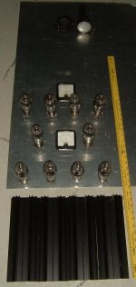
Will be able to guillotine, punch and fold it on Monday. Also found some nice 105mm X 300mm fan style heatsinks in my junk box, four of which will do nicely for the heater supply regulators.
At the top of the photo attached above the DG7-32 cathode ray tube and bezel can be seen.
Will be able to guillotine, punch and fold it on Monday. Also found some nice 105mm X 300mm fan style heatsinks in my junk box, four of which will do nicely for the heater supply regulators.
At the top of the photo attached above the DG7-32 cathode ray tube and bezel can be seen.
Attachments
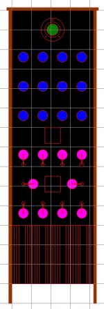
I have also finalised the layout and dimensions. Exterior dimensions are 450mm wide, 1515mm tall.
The heater supply regulator heatsinks are at the very bottom of the front panel, the 12E1 series-pass regulators tubes (purple) above, followed by the twelve KT88’s (blue) and then the DG7-32 CRT for the monitor oscilloscope.
The heater supply regulator heatsinks are at the very bottom of the front panel, the 12E1 series-pass regulators tubes (purple) above, followed by the twelve KT88’s (blue) and then the DG7-32 CRT for the monitor oscilloscope.
Attachments
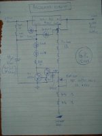
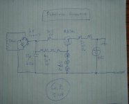
OK, I said that I was going to post up the regulator schematic this weekend, so here it goes, Sunday, 11:30pm, straight from my head to the scribble pad.
I'm pretty sure I haven't made any mistakes, but it is late and I haven't built it yet, so copy at your own peril.
The circuit provides a very low ripple, low impedance, regulated +500V for the KT88 plates from a raw ~700V unregulated supply, provided by a 500VAC transformer secondary full-wave rectified and straight capacitor filtered.
Attached below is page 1 of 3, showing the regulator section. It’s a bit of a mongrel circuit, being somewhere between / a bit of a capacitance multiplier, an emitter follower buffered zener diode and a nfb regulator.
Attachments
Well, I got my PSU chassis cut and folded up and went shopping for some of the bits that I didn’t have. Now I’m just waiting on an assortment of HV capacitors to arrive in the post. Then I can measure them up and finalise the PCB layout.
Interest in this tread has evaporated with the content getting a little more technical. Maybe the transistors in the circuit diagrams did it. If so, then this post is going to cause some distress.
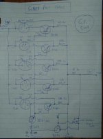
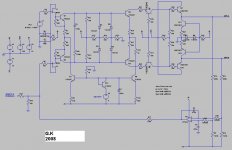
Below is a peek at the circuit for the input amplifier board. When starting out in my apprentice days I used to drool over the old school Tektronics oscilloscopes and marvel at the fully discrete and fully differential / symmetrical high-speed vertical deflection amplifier circuits and had fantasies about doing my own one day, with lots of glowing tubes at the end of the signal chain to make a big audio amplifier. So here it goes.
Differential JFET inputs are provided, so no input bias current and no capacitors in the negative feedback path.
The complementary differential outputs can each swing about 240V peak-peak. Voltage Gain is 700 for a differential output of 140V at about 0.03% THD with a 100mV peak input voltage. The uncompensated –3dB bandwidth is 1MHz.
DC balance of the entire chain is actively nulled with an opamp based DC servo.
The low impedance complementary outputs of this circuit board will be capacitively coupled to three MOSFET source followers each – one for each of the six KT88’s used per channel. The MOSFET’s will be directly coupled to the KT88’s grids (like in tubelabs Powerdrive circuit) and biased by the microcontroller board.
Interest in this tread has evaporated with the content getting a little more technical. Maybe the transistors in the circuit diagrams did it. If so, then this post is going to cause some distress.
Below is a peek at the circuit for the input amplifier board. When starting out in my apprentice days I used to drool over the old school Tektronics oscilloscopes and marvel at the fully discrete and fully differential / symmetrical high-speed vertical deflection amplifier circuits and had fantasies about doing my own one day, with lots of glowing tubes at the end of the signal chain to make a big audio amplifier. So here it goes.
Differential JFET inputs are provided, so no input bias current and no capacitors in the negative feedback path.
The complementary differential outputs can each swing about 240V peak-peak. Voltage Gain is 700 for a differential output of 140V at about 0.03% THD with a 100mV peak input voltage. The uncompensated –3dB bandwidth is 1MHz.
DC balance of the entire chain is actively nulled with an opamp based DC servo.
The low impedance complementary outputs of this circuit board will be capacitively coupled to three MOSFET source followers each – one for each of the six KT88’s used per channel. The MOSFET’s will be directly coupled to the KT88’s grids (like in tubelabs Powerdrive circuit) and biased by the microcontroller board.
Attachments
Interest in this tread has evaporated with the content getting a little more technical. Maybe the transistors in the circuit diagrams did it.
Well, you can't accuse me of being put off by the presence of solid state in a tube circuit. OTOH, my goodness, such a complex circuit to do such a simple thing!
My guess that with that super Jfet and subsequent high speed driver (ideal), the high speed b/w stuff slows down with the b/w limitations of the output transformer. Instead of ss, I used RF tubes ECF80 and 12BY7 and had to stop down the response to avoid ringing in the output stage. In your design, be very interesting how square wave looks when completed.
richj
richj
- Status
- This old topic is closed. If you want to reopen this topic, contact a moderator using the "Report Post" button.
- Home
- Amplifiers
- Tubes / Valves
- Hammond 1650W