I'm used to dealing with op-amps in a solid state world, so how do I calculate the output impedance of a single gain stage using a 12AX7 so that I have a reference point I am familiar with? And for that matter what about the output impedance of a cathode follower stage?
Thanks
Dave
Thanks
Dave
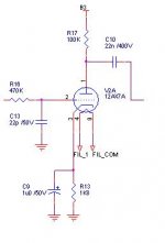
The quick answer to "Output resistance of a 12AX7?" is, "More than you'd ever believe!" Typically, 75k. Sometimes more. To find the output resistance properly, we'd need a diagram.
As for a cathode follower: (ra + RL)/(mu + 1). Assuming the supply impedance seen at the anode is zero, that approximates to 1/gm if mu is high.
As for a cathode follower: (ra + RL)/(mu + 1). Assuming the supply impedance seen at the anode is zero, that approximates to 1/gm if mu is high.
Mu is amplification factor, i.e., the change in plate-cathode voltage divided by change in grid-cathode voltage at constant current.
The circuit you attached is a common cathode voltage amplifier. Its source impedance will be 100k in parallel with the plate resistance of the tube (since the cathode is at AC ground). The latter is something like 60-80k, as EC8010 says.
My relentless plug: get a copy of "Valve Amplifiers" by Morgan Jones. Pictures, equations, thorough explanation of terms with lots of examples.
- Status
- This old topic is closed. If you want to reopen this topic, contact a moderator using the "Report Post" button.