Cacode gain. Did I do something wrong?
Greetings All,
Last year, I was playing with the attached cascode circuit. The tubes are 6DJ8 / 6922. According to the theory, the gain is high. However, I could not get a gain higher than 30, which the mu of these tubes. Have I missed something? Theoretically, the gain can reach mu squared (900).
Thanks for your input and help.
Serge
Attachments

You'll never see anything like 900. The gain is the product of the gain of the bottom tube times the gain of the top tube. The bottom tube is working into a very low resistance load, so its gain is pretty low. The top tube's load is none too big, either.
Bypassing the cathode resistor (or using LED bias) will pump the gain up a bit, but an ECC88 cascode is more likely to have a gain in the 80-100 range.
Bypassing the cathode resistor (or using LED bias) will pump the gain up a bit, but an ECC88 cascode is more likely to have a gain in the 80-100 range.
Let's look at the last example in your table. You've got 4mA of current. The cathode resistor is 810R. Plate resistor is 33k. At that current, the plate resistance is about 5k. But the effective plate resistance of the bottom tube is 5k + (mu + 1)0.810k, or nearly 30k.
Now, the cathode impedance of the upper tube is the total plate resistance divided by mu, or about 1k. The bottom tube is running less than unity gain!
Now, the cathode impedance of the upper tube is the total plate resistance divided by mu, or about 1k. The bottom tube is running less than unity gain!
Hello!!!
Hi Serge
I see that lots of questions asked here are of the 'broken record' type: every now and then they appear again, and well, most of the times the answers are the same. If not a straight answer, a refference where you can get it. In the case of the cascode with a E88CC your best bet is Valve amplifiers by Morgan Jones. Maybe you have it, so you can check pages 94-100. Now I did just a fast scan, and the example gives a gain of about 200 with 1.34mA and 100k plate resistor.
(It seems quite plausible that, although the cathode of the bottom valve is at 2.5V and therefore accepts a signal of 1VRMS without clipping, the output of the stage - which is fed from 285V - won't produce a 200VRMS swing.)
Hope this helps!
Erik
Do. I can't recommend it enough. It's $A90 from Evatco but should be less from Amazon or the like.Serge66 said:I'll buy the Morgan Jones book. Sounds like a good investment.
Re: Cacode gain. Did I do something wrong?
A gain of u^2 is highly theoretical, and basically a rough estimate. You'll never see anything like that. It's like saying that the u-factor of a 12BY7A is 1100. No way will you ever get close to a gain that high with a single 12BY7A stage. Not gonna happen.
Still, a gain of 30 is pretty pathetic. There are a number of problems with that schemo. V1a operates as a grounded grid stage. You need to lose that R10. You also need to bypass its grid to AC ground (and make sure you're generous with the bypass capacitor) and make sure that you keep the wiring in that part of the circuit as short as possible. The cascode is quite capable of very high gains, and that always means a possibility of instability. Adding impedance to the grid will compromise the gain, and make the thing very liable to RF instability. This is why most UHF triodes designed for grounded grid service (the only way the thing will work at all at extreme frequencies) come in nine-pin miniature pinouts with four or five connections to the grid; these are supposed to be parallel connected to the ground plane to minimize as much as possible any grid-to-ground impedance.
Given that, are you sure it isn't oscillating? An overlooked RF oscillation will also rob AF gain.
Serge66 said:Last year, I was playing with the attached cascode circuit. The tubes are 6DJ8 / 6922. According to the theory, the gain is high. However, I could not get a gain higher than 30, which the mu of these tubes. Have I missed something? Theoretically, the gain can reach mu squared (900).
Thanks for your input and help.
A gain of u^2 is highly theoretical, and basically a rough estimate. You'll never see anything like that. It's like saying that the u-factor of a 12BY7A is 1100. No way will you ever get close to a gain that high with a single 12BY7A stage. Not gonna happen.
Still, a gain of 30 is pretty pathetic. There are a number of problems with that schemo. V1a operates as a grounded grid stage. You need to lose that R10. You also need to bypass its grid to AC ground (and make sure you're generous with the bypass capacitor) and make sure that you keep the wiring in that part of the circuit as short as possible. The cascode is quite capable of very high gains, and that always means a possibility of instability. Adding impedance to the grid will compromise the gain, and make the thing very liable to RF instability. This is why most UHF triodes designed for grounded grid service (the only way the thing will work at all at extreme frequencies) come in nine-pin miniature pinouts with four or five connections to the grid; these are supposed to be parallel connected to the ground plane to minimize as much as possible any grid-to-ground impedance.
Given that, are you sure it isn't oscillating? An overlooked RF oscillation will also rob AF gain.
Miles, R10 is a grid-stopper. Why get rid of it? It will have no effect on the gain and may be helpful for stability.
The grid is bypassed to ground via the 90V supply. Yes, another cap there would be nice, but that's not the problem.
Nor is oscillation. The circuit is giving just the gain you'd expect given the cathode degeneration of the bottom tube and the low load of the upper tube.
The grid is bypassed to ground via the 90V supply. Yes, another cap there would be nice, but that's not the problem.
Nor is oscillation. The circuit is giving just the gain you'd expect given the cathode degeneration of the bottom tube and the low load of the upper tube.
SY said:Miles, R10 is a grid-stopper. Why get rid of it? It will have no effect on the gain and may be helpful for stability.
It's a grounded grid stage. The grid is already at 0Vac. There is nothing to stop there. Furthermore, adding impedance to the grid circuit of a grounded grid causes gain decreasing degeneration, and promotes RF instability. That internal r(b) is why grounded base amps aren't nearly as stable as grounded grid amps, and why a grounded base amp must operate into a purely resistive load to be unconditionally stable.
The grid is bypassed to ground via the 90V supply. Yes, another cap there would be nice, but that's not the problem.
What's its internal impedance? He doesn't say and doesn't provide a schemo of the 90V supply.
Nor is oscillation. The circuit is giving just the gain you'd expect given the cathode degeneration of the bottom tube and the low load of the upper tube.
He already said that he forgot to add the capacitor to the schemo, but that he did bypass the cathode resistor.
Sy,
You are correct. There is no bypass of the lower cathode.
Myles,
The 90V is provided by means of an LM317. There is a small cap on the O/P. Something like 330nF. It was last year, short memory.
I have just ordered the Valve Amps by Morgan Jones.
I will experiment with LED bias.
Has anyone tried the TL413 for biasing? Minimum voltage is 2.5V, but this IC has a very low impedance (shunt reg).
I will also try that in a future circuit.
Thanks Guys,
Serge
SY said:There's no degeneration from the grid-stopper. No current, right?
Wrong. According to the ARRL Handbook:
In the grounded grid amplifier the input signal is applied between the cathode and grid, and the output is taken between the plate and grid. The grid is thus the common element. The AC component of the plate current has to flow through the signal source to reach the cathode.
Put an impedance between the grid and ground, and you have a current loop that's common to both the input and output. That makes for instability.
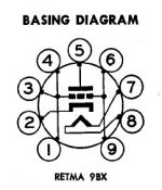
Here's the pinout for the 6AM4. There's five connections to the grid there. This was intended for use at frequencies in excess of 400MHz, and at that frequency, it won't work as anything other than a grounded grid since the Cmiller would be much too great. The way it needs to be used is for all those grid connections to be soldered directly to the ground plane. The idea is that five parallel connections will reduce the impedance between grid and ground as much as possible. Otherwise, it won't work at all. Grid stoppers for a grounded grid aren't necessary, and are a really bad idea.
Attachments
The sort of grounded grid amp in the Handbook is a classical RF type, usually zero bias, lots of grid current. Class B.
Hardly the case here, eh? Absent massive overload, there is no grid current, hence no degeneration across that resistor.
edit: To be clear, I'm not saying that grid stoppers are necessary or a good idea in that position. I'm saying that in a voltage amp, they don't make much difference at less-than-UHF and that they certainly are not degenerative.
hey-Hey!!!,
The cascode is basically a constructed pentode, and therefore gain is set by lower tube gm( at the operating point ) * the upper element plate load. It doesn't matter if the upper tube is a triode or a MOSFET...bottom element* upper element plate load.
With pentodes, there is little limit to gain. Practical things like output Z put the brakes on. If it were mu-squared, high gain circuits would use two 12AX7, instead of an element capable of high gm in the bottom position. Look at the curves for such tubes as the 6BK7B or 6BQ7A. After the sloped, 'here-be-monsters' part at less than 2x the upper element's grid voltage, the curves are pentode-like horizontal.
Question for the class: given horizontal 'plate' curves, how is gain determined? Hints: horizontal curves indicate a gm device, setting pass current depending on control grid voltage.
cheers,
Douglas
The rough calc for gain is gm (lower) times RL (upper) as Erik and I said before. You just have to use the effective gm, which includes degeneration. That gives you the right number for the example we worked out, and with an LED or bypassed Rk, we predict about 200. Serge will no doubt tell us about it.
I tried a crazy cascode trick circuit from Tim de Paravicini, ECC88 at very low current (and consequently low gm) and a high plate resistor (510k). It worked surprisingly well; at 5V out, second harmonic was -58dB, and all others were below anything I could measure.
Of course, the output impedance is impractically high unless intimately paired with a cathode follower...
SY said:The rough calc for gain is gm (lower) times RL (upper) as Erik and I said before. You just have to use the effective gm, which includes degeneration. That gives you the right number for the example we worked out, and with an LED or bypassed Rk, we predict about 200. Serge will no doubt tell us about it.
I tried a crazy cascode trick circuit from Tim de Paravicini, ECC88 at very low current (and consequently low gm) and a high plate resistor (510k). It worked surprisingly well; at 5V out, second harmonic was -58dB, and all others were below anything I could measure.
Of course, the output impedance is impractically high unless intimately paired with a cathode follower...
No, this is what you said before:
The gain is the product of the gain of the bottom tube times the gain of the top tube.
No mention of gm anywhere. Just so we're clear...
")
cheers,
Douglas
- Status
- This old topic is closed. If you want to reopen this topic, contact a moderator using the "Report Post" button.
- Home
- Amplifiers
- Tubes / Valves
- Cascode gain. Did I do something wrong?