Steven-H said:Interesting Stuff ! How do you keep tabs on your battery voltage though ? I would imagine that as the batteries age - that your bias would change ?!
For the filament supplies, I bought the TentLabs 5A supplies. So I suppose that I would connect them to the cathode, then ground one side out right at the tube pin ?
Also - while I have your eyes - I thought that the IT needed to be loaded somehow ?
Lets see if this schematic looks correct....
No, the bias doesn't change that much. I check it every year. Just replace the batteries when they get old. They last as no current is flowing.
I hope my schematic makes the wiring clear
Ciao
Gianluca
An externally hosted image should be here but it was not working when we last tested it.
Guys,
Ok - so; thanks to all of your help it is now becoming clear. Are there any octal tubes that would be a single triode equivalent to the 5687 ?
So I am going to populate the tubelab board, and just mount the sockets to the chassis with short leads to the PCB.
I hope to start the build within a month or so (work is just way to busy); once I nail down the input tube I will be able to make up my top plates for the PSU and the actual amp.
Thanks again,
Steve
5687 came out during the space travel era and therefore doesn't have an obvious octal equivalent. Electro-Harmonix makes an octal version of the 6H30 (which is very similar to 5687) if you really want octal. The 6BX7 is probably the closest original octal to the 5687, in the sense that it is higher gm, but it has much lower mu (~8) and isn't as linear (reportedly).
Paul,
Thanks ! I read through tubelab's site, and found the operating points that he used for the driver section (12mA CCS, 180v), and mapped 'em out on the 6BL7 curves. Using Josh's recommendation of 275v:
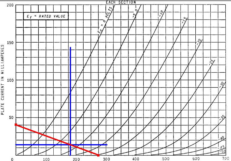
My only concern here is that the 5842 consumes 300mA of heater current (600mA per pair), while the 6BL7 is 1.5A; so I may have to stick with AC on the heaters for 'em (as I might melt down the heater supply on the board). Everything else I think looks OK.
Onto the power tube. Most schematics I have seen grid bias the tube @ -90v (grey line). As Gianluca helped me out with earlier; I would be right there @ -89v if I used 7 of those 12v batteries (Q=750v@28mA). However, in looking at his schematic, he is at -77v (6 12v batteries, plus the 5v from the heater - blue line). I don't think it would make too much of a difference ?
As an amp of this voltage wouldn't be a candidate for a triode-mode switch, I suppose I can easily add/remove a battery when I solder in my resistor, etc
Look OK ?
Thanks guys,
Steve
Thanks ! I read through tubelab's site, and found the operating points that he used for the driver section (12mA CCS, 180v), and mapped 'em out on the 6BL7 curves. Using Josh's recommendation of 275v:
My only concern here is that the 5842 consumes 300mA of heater current (600mA per pair), while the 6BL7 is 1.5A; so I may have to stick with AC on the heaters for 'em (as I might melt down the heater supply on the board). Everything else I think looks OK.
Onto the power tube. Most schematics I have seen grid bias the tube @ -90v (grey line). As Gianluca helped me out with earlier; I would be right there @ -89v if I used 7 of those 12v batteries (Q=750v@28mA). However, in looking at his schematic, he is at -77v (6 12v batteries, plus the 5v from the heater - blue line). I don't think it would make too much of a difference ?
An externally hosted image should be here but it was not working when we last tested it.
As an amp of this voltage wouldn't be a candidate for a triode-mode switch, I suppose I can easily add/remove a battery when I solder in my resistor, etc
Look OK ?
Thanks guys,
Steve
Nope. Assuming you're intending to bias at say 900V B+ and 85mA, find that point on the curves, then draw the 6K loadline. It will swing well above the 900V B+. Eyeballing your curves, at the Q point I mentioned Vg = -95V.Steven-H said:Onto the power tube. Most schematics I have seen grid bias the tube @ -90v (blue line). As Gluica helped me out with earlier; I would be right there @ -89v if I used 7 of those 12v batteries (Q=750v@25mA). However, in looking at the curves dead center (grey line), I think that in triode mode anyway; I would be better off with my Q=580v@50mA:

Brett -
Thanks, as usual I was doing something wrong...
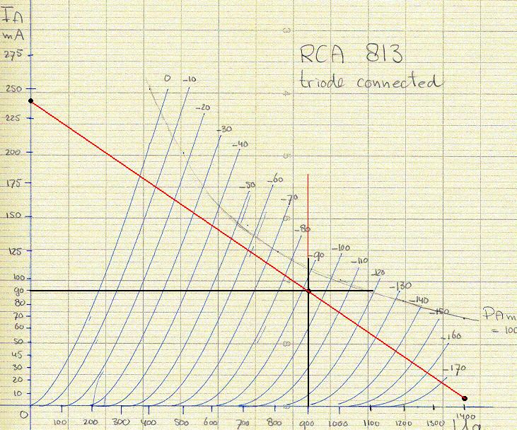
So, now my bias point isn't neatly fitting into multiples of 12 (Q=900v@90mA). Once I get the PSU breadboarded and find out my true B+ I suppose the best way to get the bias where I need it to be would be by adding some 1.5v batteries.
Thanks, as usual I was doing something wrong...
So, now my bias point isn't neatly fitting into multiples of 12 (Q=900v@90mA). Once I get the PSU breadboarded and find out my true B+ I suppose the best way to get the bias where I need it to be would be by adding some 1.5v batteries.
That picture I posted is from an amp running the GM70, ok ... I was cheating  . I changed a while ago the output tube.
When I used the 813, it was running at 750V/100mA and I believe I used 6 batteries. In case you cannot fix the bias with multiples of 12V you can still use a center tap resistor at the filament (bias would be just like AC, i.e. 6*12V=72V) or a small resistor under the cathode. I usually don't care if the plate current is +/-5ma away from ideal. Another option is to ground the +terminal of the DC filament so the bias will be 6*12-5=67V. Old datasheets suggest to tie the -terminal of the DC filament to ground but I can't see any difference and I did it without any issue.
So you can bias the 813 at 77V, 72V or 67V using 6 12V batteries.
Fine tune with a cathode small unbypassed resistor if you like. Keep in mind the whole filament current will be passing through the resistor so it needs to be fractions of ohm (lets say 0.47Ohm) but high power (0.47*5.1*5.1=12W). That's why I prefer to over/under bias the tube. If you use the classical hum pot at the cathode, the resistor will be passing only the plate current so it will not be dissipating such a huge power.
Easier to do than to write.
Ciao
Gianluca
. I changed a while ago the output tube.When I used the 813, it was running at 750V/100mA and I believe I used 6 batteries. In case you cannot fix the bias with multiples of 12V you can still use a center tap resistor at the filament (bias would be just like AC, i.e. 6*12V=72V) or a small resistor under the cathode. I usually don't care if the plate current is +/-5ma away from ideal. Another option is to ground the +terminal of the DC filament so the bias will be 6*12-5=67V. Old datasheets suggest to tie the -terminal of the DC filament to ground but I can't see any difference and I did it without any issue.
So you can bias the 813 at 77V, 72V or 67V using 6 12V batteries.
Fine tune with a cathode small unbypassed resistor if you like. Keep in mind the whole filament current will be passing through the resistor so it needs to be fractions of ohm (lets say 0.47Ohm) but high power (0.47*5.1*5.1=12W). That's why I prefer to over/under bias the tube. If you use the classical hum pot at the cathode, the resistor will be passing only the plate current so it will not be dissipating such a huge power.
Easier to do than to write.
Ciao
Gianluca
Gents,
Thanks again for the help. So I guess I will clearly have a whole lot more swing than necessary....
I am going to start to work on my PSU. With 141 ohm DC resistance in my OPT's I am shooting for about 915v (When I PSUD'd the design I was getting about 916v; got lucky so far...)
Thanks again for the help. So I guess I will clearly have a whole lot more swing than necessary....
I am going to start to work on my PSU. With 141 ohm DC resistance in my OPT's I am shooting for about 915v (When I PSUD'd the design I was getting about 916v; got lucky so far...)
- Status
- This old topic is closed. If you want to reopen this topic, contact a moderator using the "Report Post" button.
- Home
- Amplifiers
- Tubes / Valves
- 45 -> 813 Interstage