Some sugestions
Power transformer only 52 watts, but it loaded on 74.
It getting hot as hell.
Tube 6005 has a blue lights inside, it bad sign, vacuum was lost.
Probably of long storage period.
I made some changes, put other transformer for filament ( took off 30 Watts from the main, anyway it was overloaded, max current 4.0 when it was drained on 0.45x8 + 0.35x2 = 4.5 A ).
I also decreased resistor R12 and R25 to 80 Ohm, in original it was 150, so tube operated in class B, slightly colored to AB2 ( 100 mA / 4 tubes = 25 mA each, when spec for tubes 45 mA for A, and 35 for AB ).
The same time loaded PT again, this time up to 64 watts, I 'm thinking to get rid of this limiter...
Other thing low gain, voice from your CD would not be enought to get 16 watts output. All you can get it's around 2 watts.
I have to think about it.
Kit is very good for begining, push you to think and troubleshoot.
Open for discussion.
Sorry to dig up an old thread, but I there is good information here.
I finished this kit a while ago, but thought would let it burn in before moding it any. I like the sound quality and it was a pretty easy build, but I have a bit of a noise problem. It's isn't too noticable if the volume stays below 12 o'clock, but it is something I would like to address. It looks like replacing some caps have helped some of you in the past. Which caps helped?
Thanks,
Jake
Hi Jake,
if the noise is a buzzing sound it is likely coming from the HV rectifier.
There is a simple fix to that. VoltSecond describes it very nicely on his homepage:
http://www.siteswithstyle.com/VoltSecond/K-12M_AMP/K-12M_Push_Pull.html
If the noise is more like a humming sound it may come from the filaments. You can use a voltage divider on the HV supply generating ~30V to lift the center tap of the filaments to this level (instead of ground).
I used 1M and 100K in series from HV to ground. Parallel the 100k with a 47uF capacitor. Now connect the center tap of the filament winding to the voltage divider (should be around 20-25V at the junction of the two resistors).
This basically eliminates any AC hum on the filaments. It worked very well on my K-502 and my version of Gingertube's Baby Huey.
I hope this helps.
Martin
Hi Jake,
the capacitor would go across the two connections where the two red HV secondary wires of the power transformer are connected to the PC board. Make sure this cap has a high enough voltage rating (2kV ceramic or 600V film cap).
You can improve further by replacing the bridge rectifier with 4 UF4007 diodes. This will need a little improvisation since there is not much space on the PC board. Take a look at VoltSeconds homepage again.
The version with the snubber network might be even better (called HV snubber Version 2 on his page).
He then shows how to use a single Ultra-Fast diode in combination with the bridge rectifier, this should work also very well with above Snubber network and will improve the situation further.
I do not know how much the filament snubbers help but it is an easy thing to do and VoltSecond shows nice pictures how to do it if you can't figure it out by yourself.
Taken together, these are simple mods that improve the noise of these amps a lot.
Make sure you check and discharge ALL HV capacitors before working on the amp .
Also have a look at the sticky safety post here in the forum if you are not very familiar with high voltages already.
If the buzz is gone you can try to get rid of any hum that is still present but that is usually less annoying (sine wave).
Good luck!
Martin
Being that I have limited high voltage experience, I am going to perform the mods on my amp under the direction of my EE/HAM father-in-law. I figured it would be the safest way to go, plus he could help me figure out anything if I get stuck. I don't have time to do it until a week and a half from now, but I guess I'll just have to be patient.
I know I'm going to install the first mod (.01uF cap) and maybe more, but I'll cross that bridge when I get there.
I know I'm going to install the first mod (.01uF cap) and maybe more, but I'll cross that bridge when I get there.
In the original post, one of the upgrades suggested was: -Bigger filter caps (220 uF, 220 uF, 100 uF instead of 220, 100, 22). I might tackle this as well when I fix a few other things, but I am wondering if these have to be polarized, electrolytic caps like the originals? Also, should I stick with the stock 250v?
Hi, The caps could be non-polorized, if you can find ones big enough with enough voltage rating (rather costly as well). Polorized electrolytics are fine for this application. I would use ones of at least 350 volts rating. I use 100 uf in my amp in the third position. The caps are inexpensive, however, I suggest you not use the bottom of the line cheapies. The power supply can be considered the other half of your sound path. You want it to hold up its end of the job. There are a number of good sites on the web that explain this aspect of the power supply. Rather that repeat stuff that is elsewhere, if you want PM me. Recently, I have had good luck with "Ruby" and "JJ" brand caps. You can spend a lot more but the return on the K series of amps is probably not worth the cost.
I found these 220uf and 100uf caps for the filter caps upgrades. Am I on the right track?
http://www.partsexpress.com/pe/showdetl.cfm?&Partnumber=020-658
http://www.partsexpress.com/pe/showdetl.cfm?&Partnumber=020-656
Thanks for all the help and I'm learning more every day.
http://www.partsexpress.com/pe/showdetl.cfm?&Partnumber=020-658
http://www.partsexpress.com/pe/showdetl.cfm?&Partnumber=020-656
Thanks for all the help and I'm learning more every day.
I Learn a bit every day. Audio, especially dealing with tubes is rewarding and challanging. In spite of modeling programs, computers and lots of literature it still has an element of art involved.
The caps you selected are ones I have used in a number of projects and work well. One of my K-12s uses those exact parts. I'm glad to be of help.
The caps you selected are ones I have used in a number of projects and work well. One of my K-12s uses those exact parts. I'm glad to be of help.
Sorry for one last question,
The "270K bleeder resistors on filter caps" in the original post, where are they soldered in? If they are discharging the caps when the amp is off (which is the purpose of a bleeder I believe), I would assume that the resistor would be soldered between one of the lead of the cap and a ground maybe? Thanks for the help again.
The "270K bleeder resistors on filter caps" in the original post, where are they soldered in? If they are discharging the caps when the amp is off (which is the purpose of a bleeder I believe), I would assume that the resistor would be soldered between one of the lead of the cap and a ground maybe? Thanks for the help again.
Hi, You are correct. It doesn't have to be physically right at the cap, but it is good practice to place it there. It is put there to bleed off the charge on the caps when the power is removed. Without it, large caps (like the ones you are using) will store a potentially deadly charge for quite some time. Depending on where in the circuit you place it, there can still be a delay of several minutes before the charge on all the caps is drained to a safe level. Always assume a cap is charged. If there is any doubt, use a meter on it.
I try to warn everyone not to treat high voltages casually, please ask about any problems, concerns or just for information. Don't assume anything about tube circuits. I don't know of any diyers that would feel offended to answer such questions.
I try to warn everyone not to treat high voltages casually, please ask about any problems, concerns or just for information. Don't assume anything about tube circuits. I don't know of any diyers that would feel offended to answer such questions.
Hi, Generally, they will not have such an effect. It is possible that if the circuitry used very little current that the bleeders might act as a partial load. This is rather unlikely in a power amp though. The amp will draw many milliamperes of current and the bleeder only 1 or 2 typically. In a preamplifier circuit with very low drain tubes it would have to be considered in calculating the resistors between the power supply filters as it would have some effect on the voltage drop from section to section. For example, I have one stage in a current project that draws only 1.2ma. Because of the geometry of the stage, if the bleeder were attached at the final filter cap it would drop the voltage available to the tube by a significant amount if not included as a load on that section of the power supply filters.
Hi Jake,
in some power supplies with high HT voltages, people use capacitor with lower voltage rating in series, since they are cheaper and easier to source. In that case there are two "bleeder" resistors - one parallel to each cap. The main function of those is to make sure that each cap gets exactly 1/2 HT voltage. This is important because each single cap is not able to handle the full voltage.
They also serve as bleeder resistor when the amp is turned off.
There is no real audio function besides keeping the caps happy and therefore the power supply working and ultimately the amp running.
If you have single caps in the power supply the bleeder resistor is really only for your safety in there - and it should be there. Those caps are just waiting for this one second of sloppiness 
I'd connect them parallel to the cap right at the same spot. The resistor lead is also a good spot to attach a probe to measure voltages since the cap leads are often very short.
Martin
edit: I see that gofar99 answered simultaniously
in some power supplies with high HT voltages, people use capacitor with lower voltage rating in series, since they are cheaper and easier to source. In that case there are two "bleeder" resistors - one parallel to each cap. The main function of those is to make sure that each cap gets exactly 1/2 HT voltage. This is important because each single cap is not able to handle the full voltage.
They also serve as bleeder resistor when the amp is turned off.
There is no real audio function besides keeping the caps happy and therefore the power supply working and ultimately the amp running.
If you have single caps in the power supply the bleeder resistor is really only for your safety in there - and it should be there. Those caps are just waiting for this one second of sloppiness
I'd connect them parallel to the cap right at the same spot. The resistor lead is also a good spot to attach a probe to measure voltages since the cap leads are often very short.
Martin
edit: I see that gofar99 answered simultaniously
Hi, At the present time I'm on a DC heater kick. All the projects for the last year or so have DC. The one exception is the K-12 mods. I stuck with AC there. It could be done rather easily though, I just didn't think it would be worth the effort. The quickest and easiest way would be to use a 12 Volt SMPS. They run about $18 from several sources. I would want to (if possible)scope the output for switching noise. If not possible, a simple pair of RF chokes and a few small caps would be in order to be sure the was no trash getting into the amp. I have used similar supplies and find them trouble free. The biggest problem doing this with a K (other than a K-12) amp is rewiring the heaters for 12 Volts. The reason for 12 and not 6 is that 6 volt SMPS are scarce and more costly.
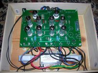
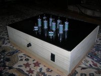
Hi, It looks pretty good to me. It is rather difficult to get the wires to transformers and jacks to look neat. I sometimes use small nylon wire ties to bundle some together. Don't bundle input and AC wires with anything though. It will cause noise and hum pickup. Nice woodwork, what is the top made of?
- Status
- This old topic is closed. If you want to reopen this topic, contact a moderator using the "Report Post" button.
- Home
- Amplifiers
- Tubes / Valves
- Review of New S-5 K-16LS Kit