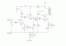
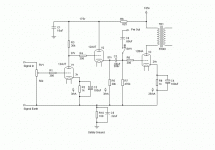
Hi all. I have designed a small amplifier for use in my small listening room. I am posting it looking for opinions and suggestions. I realize that some of you will not agree with the tubes that I have chosen and that is OK with me. I think it will work and sound fine but I wanted to make sure that it is as polished as it can get in spite of the crappy tubes I chose.
Attachments
470k gridleak is kinda high, and a .68µF / 470k is almost going to let DC through, hehe... (rolloff is like 0.5Hz... go to 100k or something.)
That and I hate direct coupled stuff, I'd cap couple it and put in a divider to bias the CF... or drop it altogether, an AU7 shouldn't have a problem driving a 12B4, I wouldn't think... but whatever.
You could parallel the AU7 and have plenty of drive, if you want to use the whole tube. or if it's stereo, use 1/2 a channel.. or something like that.
have fun
Colt45 said:470k gridleak is kinda high, and a .68µF / 470k is almost going to let DC through, hehe... (rolloff is like 0.5Hz... go to 100k or something.)
That and I hate direct coupled stuff, I'd cap couple it and put in a divider to bias the CF... or drop it altogether, an AU7 shouldn't have a problem driving a 12B4, I wouldn't think... but whatever.
You could parallel the AU7 and have plenty of drive, if you want to use the whole tube. or if it's stereo, use 1/2 a channel.. or something like that.
have fun
The reason for the CF is to drive a subwoofer amp in parallel with the output stage. Also I would think that a .68uF cap into a appoximately 50K load(when driving two loads in parallel) would be a big enough coupling/output cap. I can make the cap as big as needed. I left the 470K grid leak in to keep the input impedance of the total load I will be driving as high as possible.
pmillett said:Looks pretty sensible to me. Build it and see how it works!
Pete
Do you see any problem with it (the modified Foreplay part) drivng a subwoofer amp and the output section in Parallel Pete? Do I have the coupling cap sized too small for a 50K load?
pedroskova said:...kinda looks like the original Bottlehead Foreplay circuit driving the 12b4, which benefited from ccs(source) loading of the VA section, and ccs(sink) on the CF.
If I were building a little 12b4 amp, I would be tempted to go push-pull.
It is basically the original Foreplay circuit with a few changes of the operating points. I plan on building the SE version on a rather large chassis (17x10) and if I don't get enough volume out of my full ranger speakers then I can modify it as a PP amp. I could use the CCS boards on it but I really don't need all of the gain. The output stage will only take 48v PP before clipping. This is designed with efficient speakers and a small room in mind. 95 dB from a full ranger in a small room is loud.
Not as long as the sub amp is well-behaved. I'd be a little worried that it might inject some DC back into the grid of the 12B4.
A safer bet would be to use two coupling caps - maybe a 0.1 or 0.22 to the 12B4, and a seperate .68uF or 1uF to the sub amp.
You could even try taking the 12B4 cap to the plate of the first 12AU7 (bypassing the CF) - I don't think it would have too much trouble driving the 12B4 directly.
I didn't calculate what gain you'll wind up with, but I expect it will be a little low. Might be fine for your system. If you need more gain you could swap in a 12AT7 or something else (5687/7119 come to mind).
Pete
pmillett said:Not as long as the sub amp is well-behaved. I'd be a little worried that it might inject some DC back into the grid of the 12B4.
A safer bet would be to use two coupling caps - maybe a 0.1 or 0.22 to the 12B4, and a seperate .68uF or 1uF to the sub amp.
You could even try taking the 12B4 cap to the plate of the first 12AU7 (bypassing the CF) - I don't think it would have too much trouble driving the 12B4 directly.
I didn't calculate what gain you'll wind up with, but I expect it will be a little low. Might be fine for your system. If you need more gain you could swap in a 12AT7 or something else (5687/7119 come to mind).
Pete
This is the point where my ignorance starts to really embarrass me. THe datasheet for the 12AU7A shows a "amplification factor" of 20. Will I get a voltage gain of 20 out of this circuit? If not then you are correct in that I will have to choose another tube. I would like to get as close as I can to swinging 48v PP into the 12B4A without driving it into clipping. I bought four "Vitamin Q" .68uF caps for this project so I can use one to the sub amp and one to the output stage without a problem. I can also resize the grid leak resistor on the 12B4A to something a little smaller if you feel that it is needed with the .68uF cap but I would like to use the caps I bought.
pmillett said:Not as long as the sub amp is well-behaved. I'd be a little worried that it might inject some DC back into the grid of the 12B4.
<snip>
Pete
That was one of my concerns as well, however I see it has been addressed.
How would the input of the sub amplifier behave with a 40Vpp waveform at its input if you drove the 12B4 to approximately full output?
I would consider buffering the subwoofer output separately and directly from the volume control. Perhaps you could dispense with the existing CF stage and drive the 12B4 directly with 1/2 of the 12AU7, use the other half for a unity gain buffer (CF) off of the volume control to drive your sub amplifier.
Also the 12AU7 has better linearity and sound at somewhat higher currents - I'd recommend something > 5mA..
kevinkr said:
That was one of my concerns as well, however I see it has been addressed.
How would the input of the sub amplifier behave with a 40Vpp waveform at its input if you drove the 12B4 to approximately full output?
I would consider buffering the subwoofer output separately and directly from the volume control. Perhaps you could dispense with the existing CF stage and drive the 12B4 directly with 1/2 of the 12AU7, use the other half for a unity gain buffer (CF) off of the volume control to drive your sub amplifier.
Also the 12AU7 has better linearity and sound at somewhat higher currents - I'd recommend something > 5mA..
My subwoofer amp has a built in attenuator so I had planned on just dialing it way back and hoping for the best. I'm driving it now with basically the same circuit so I don't anticipate any problems.
As far as the 12AU7 goes I agree that a little more current would increase the linearity but it would cut back on the headroom at the input of the amp. I have sacrificed linearity for headroom. Hopefully the tradeoff is not too drastic.
G said:THe datasheet for the 12AU7A shows a "amplification factor" of 20. Will I get a voltage gain of 20 out of this circuit?
Nope. You can approach getting the "amplification factor" with a CCS on the plate - with a resistive load you'll get quite a bit less. I'm too lazy to work it out but I would guess you'll get a gain of closer to 12.
Pete
pmillett said:
Nope. You can approach getting the "amplification factor" with a CCS on the plate - with a resistive load you'll get quite a bit less. I'm too lazy to work it out but I would guess you'll get a gain of closer to 12.
Pete
Well that sucks. So that would mean that I won't get all of the potential output out of the 12B4A that I would if I used a higher gain tube right? I could use a 12AT7 but then I would risk my source clipping the input. Interestin' conundrum. I suppose I could just use CC sources but even then I wouldn't get enough gain to push the 12B4A to full potential output.
- Status
- This old topic is closed. If you want to reopen this topic, contact a moderator using the "Report Post" button.
- Home
- Amplifiers
- Tubes / Valves
- Thoughts and suggestions needed.

