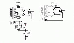
Heater supply options and to Vhk rating of 6x4 & 6203
I’m in the process of building the power supply of a small preamp and would like some advice.
I have a 300-0-300 V trannie to be used in a choke input (30H 205 ohms) supply with a 6203 rectifier. I also have a separate 6.3V 1A filament supply. The data sheet for the 6203 states peak Vhk = negative 450 V& positive 100V
Connecting the filament supply to the 6203 seems like it’s going to exceed this rating so:
Option 1; float the heaters using voltage divider, but what voltage should I reference it to ?
Option 2: some say to it is even better to run the rectifier from a separate heater supply, connect it directly to the cathode and run it like a directly heated cathode rectifier.
Can this be done with the separate XF or should it be from a heater winding of the same power XF.
I plan on using a current regulated LM317 supply for the preamp valve heaters
I’d like to know what others have done and what would be the best option
Cheers
Richard
Attachments
The approx output from a 300-0-300 supply with choke input will be 300*0.9-30 = 240 VDC, so you should be fine with the filament supply at ground potential. Use the 450 volt rating when the cathode is above heater potential, and vice versa.
The ratings are different because when the heater is above cathode potential, electrons can flow to it like as if it was a plate, grid, etc... while if it is below cathode potential, electrons will not be attracted to it.
The ratings are different because when the heater is above cathode potential, electrons can flow to it like as if it was a plate, grid, etc... while if it is below cathode potential, electrons will not be attracted to it.
HI Boris,
Thanks once again, I'll go with that suggestion.
EC8010,
Thank you for checking that detail. I've done a few kits in the past to cut my teeth but this is my first circuit build from scratch.
The current draw for the circuit is about 3mA/channel at 200V.
The RDH indicates inductance is approx load R/940 for 50Hz supply so:
R = 200V/0.006 mA = 33.33K
L= 33.33K/940 = 35H
But I'm also using 2 x 5787 VR tubes/channel that draw 10mA/channel, hence total current draw is about 26mA, this should decrease the minimum inductance.
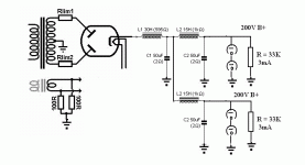
I've modelled the attached supply in PSD II, I hope I'm on the right track
Cheers
Richard
Attachments
Glad to see those resistors. That looks as though it ought to be fine. Don't forget to test in PSUD what happens when the incoming mains drops by 6% or so (to make sure it still all works). Also, try the step load in PSUD to make sure LF stability is OK, and have a look at currents.
Gentlemen,
I did some more modeling in PSUD (circuit as in post #6).
I first simulated a ccs, using the stepped load 20mA to the vr tube (10mA each) and then after 3 seconds an additional 6mA to the circuit (3mA each). Voltage at the load was about 228V then dropped to about 217V. Putting a 20mA current tap between L1 & L2 and drawing a load current of 13mA after L2 (to simulate the 13 mA/channel) produced very similar results.
I then simulated a resistive load, as the PSU is split into 2 channels after C1 I used a 16K load (approx 220V/0.013mA). This yielded 233V at C2.
To simulate variations in mains, I calculated a 6% drop in 240V mains to be 225V, if the equivalent drop in XF secondary output is 18 volts I modeled 282V. Voltage at the load came out to be about 220V.
My concern is if a minimum of 220V prior to the vr tubes is enough to allow them to ignite. The datasheet indicate that the ambient light starting voltage is 135V (150 in total darkness), what starting voltage is necessary if 2 tubes are stacked in series?
Rich out
ok, its back to the drawing board.
220V is not going to light those buggers, luckily I also managed to scavenge another XF, this one has a 350-0-350 secondary.
The infinite wisdom of PSUD2 indicates 261.3V to 268.9V after all those chokes, that should be enough to get them burning. I hope this increased V doesn’t get the heater cathode insulation of the 6203 burning.
I’m still waiting on the 30H choke. Should be able to start building this weekend I’ll post some sexy pics when it’s done.
Cheers
Richard
- Status
- This old topic is closed. If you want to reopen this topic, contact a moderator using the "Report Post" button.
- Home
- Amplifiers
- Tubes / Valves
- Heater supply options and to Vhk rating of 6X4 & 6203

