Poindexter:
I only used the DC supply because it was all I had to hand. If I had a 6.3V traffo I would have used that first....
The voltage is adjustable from about 4.5 to 6.7 or so, so its an easy matter to turn it down to 6.2. I'm going to use this supply to run a LDR type attenuator as well (at least for try out anyway) and 6.2 would suit very well there too.
There is no centre tap with the DC supply, but I put in a virtual one with 2 100r and have that raised at about 26-27V (actual measurements) off the b+ as per schematic (was it 26K-120K or something for the divider?).
I'm hoping to do the various other bits tonight, knobs etc and get it mounted up. If I get it done, I'll try it out inside.
Fran
Brett said:The Rdrop resistors are to tweak the voltage at the filaments to exactly 6.3V in use when warm. The power Tx will vary a bit depending upon size and it's inherent regulation as well as variations in local mains supply voltage.
Curiosity question, the rDrops are symmetrical on the schematic, one on each side. Does that really have to be that way or does it just have to get the VAC to 6.2 and with reasonable DC offset from the main power?
No. I do that to minimize the dissipation in the resistor if the total resistance gets above 0.3Ω or so, because I don't like to have stuff that hot in the chassis. The heater circuit, especially in a power amp, can draw several amps of current. I have a bunch of Ohmite inductive 2W wirewounds from Digi-Key in 0.1Ω and 0.25Ω, and I just take my best guess at it, then calculate in from the initial voltage.
I saw this in a very early issue of Sound Practices, a graph of statistical tube lifetime versus heater voltage/rating, compiled by one of the bigs, GE or somebody. The correlation was striking; if a 6.3v tube was operated at 6.5v or so, it's statistical lifetime was reduced about 50%, and if operated at ~6.1v, increased by 50%, on a pretty linear slope. The downslope for higher voltage never levelled off, and the upslope for reduced heater voltage didn't level off until the device stopped working correctly. The burden of the exposition being, of course, that heater voltage was a (maybe the) major determinant.
I operate all my devices inside all their ratings, and reduce the heater voltage a percent or two from rating, and I'm getting about 30,000-40,000 hours from output tubes, and essentially indefinite lifetime from the small-signal ones.
Aloha,
Poinz
This bird sings!
Some measurements:
B+ 136V
Heaters floated 24V off ground.
Attenuation is via a LDR, which BTW eliminated the last trace of hum (not that I could hear it at more than 2ft from speakers)
LHS lower valve:
K to gnd 1.3V
A to gnd 71V
RHS lower valve:
K to gnd 1.5
A to gnd 75V
LHS top valve:
K to gnd 72.5
RHS top valve:
K to gnd 76.4V
Heaters now adjusted to 6.2V
I'm slightly abusing the K to heater by a couple of volts, but hey the tubes are cheap.
Sound is very clear and clean, but need to listen more to get real impressions. Just a nice amount of gain. I am a happy camper!
For some reason my DMM won't measure current so I don't know what the draw is. I did go back and solder in the 68R/75R instead of the 75R/82R of the schematic. No real difference in sound though.
Fran
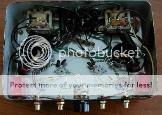
No, don't know why that is. Its on the to-do list. The B+ comes via one wire to the upper valve of one side and then daisy chained on to upper valve of other side. If you have a look in the picture I posted back up a bit, its the red wire coming from the filter cap to the valves (hard to see I know).
And its unlikely to be the valves either because I've had them in and out a few times and have been mixed up everyway.
Since boxing it up I now have a buzz- I have to go back and have another look, its like the buzz when the signal ground is connected to the chassis. I didn't change anything when I boxed it up, but the volume control might be touching the chassis plate maybe.
Will know more tonight and will post details of the rest of the system.
Fran
OK, got the buzz sorted out. It was a bad diode in the ground breaker. Put in a new set of diodes and all is well. As a result I had no break between circuit ground and earth. I knew it sounded like mains buzz.
So the amp is in situ and working very nicely. Still too early to really tell vs. the aikido, but it does sound very nice. I'd be inclined to think that there isn't very much between them. I'll need more ears than mine and a direct AB to really tell more. I don't feel as if I'm missing anything though. given the simplicity of this circuit, I would say it would be an excellent choice for someone starting off. The voltage is that bit lower too. Parts are few and the valves are cheap and the sonics excellent. It would certainly be easier and most likely cheaper to build than an aikido (although if you were building that on a PCB it might be the same level of difficulty). In real terms the chassis work is the only thing stopping anyone for having a go at this.
So someone asked about the rest of the system:
Sources:
Teres 340/RB300/Benz micro L2/phonoclone
Rebuilt Lenco/DIY unipivot/zyx R50 bloom/phonoclone
Eastsound CD E5 CDP
Squeezebox/Zhaolu 2.5C DAC/linear PS
Either 6T4 or 24V aikido preamps
SYs RLD district EL84 amp
Quad ESL57 speakers
Pic:
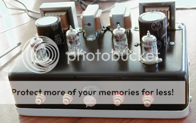
And a few more pics of the amp:
GEC valves are in the amp at the moment. Outputs caps are wimas MKP and the resistors are all 1% metal film from mouser. B+ Tx is a large toroidal 240:110 job and the PS is 47uF:double choke:120uF:560R:470uF(all electrolytics). B+ is at 135-137VDC, heaters are DC at 6.2V. Selector switch is gold flashed 4pole 6 way off ebay, RCA jacks the same. All circuit wire is solid core 20G silver in teflon. Wire from RCA to selector is 24G stranded silver in teflon twisted pair.
I'm kind of regretting now that I didn't make more of an effort with the chassis. It looks better in real life than the photo, but still. Another point - I used a LDR for the volume control (see the lightspeed attenuator thread over in solid state) so I don't know if that makes this an unfair comparison to the aikido which has a stepped pot. The LDR is very clear and neutral though and streets ahead of the alps blue which I had in there for testing. Never going to use a pot like that again for volume if I can help it.
Fran
So the amp is in situ and working very nicely. Still too early to really tell vs. the aikido, but it does sound very nice. I'd be inclined to think that there isn't very much between them. I'll need more ears than mine and a direct AB to really tell more. I don't feel as if I'm missing anything though. given the simplicity of this circuit, I would say it would be an excellent choice for someone starting off. The voltage is that bit lower too. Parts are few and the valves are cheap and the sonics excellent. It would certainly be easier and most likely cheaper to build than an aikido (although if you were building that on a PCB it might be the same level of difficulty). In real terms the chassis work is the only thing stopping anyone for having a go at this.
So someone asked about the rest of the system:
Sources:
Teres 340/RB300/Benz micro L2/phonoclone
Rebuilt Lenco/DIY unipivot/zyx R50 bloom/phonoclone
Eastsound CD E5 CDP
Squeezebox/Zhaolu 2.5C DAC/linear PS
Either 6T4 or 24V aikido preamps
SYs RLD district EL84 amp
Quad ESL57 speakers
Pic:
An externally hosted image should be here but it was not working when we last tested it.
And a few more pics of the amp:
An externally hosted image should be here but it was not working when we last tested it.
An externally hosted image should be here but it was not working when we last tested it.
GEC valves are in the amp at the moment. Outputs caps are wimas MKP and the resistors are all 1% metal film from mouser. B+ Tx is a large toroidal 240:110 job and the PS is 47uF:double choke:120uF:560R:470uF(all electrolytics). B+ is at 135-137VDC, heaters are DC at 6.2V. Selector switch is gold flashed 4pole 6 way off ebay, RCA jacks the same. All circuit wire is solid core 20G silver in teflon. Wire from RCA to selector is 24G stranded silver in teflon twisted pair.
I'm kind of regretting now that I didn't make more of an effort with the chassis. It looks better in real life than the photo, but still. Another point - I used a LDR for the volume control (see the lightspeed attenuator thread over in solid state) so I don't know if that makes this an unfair comparison to the aikido which has a stepped pot. The LDR is very clear and neutral though and streets ahead of the alps blue which I had in there for testing. Never going to use a pot like that again for volume if I can help it.
Fran
Measurements were taken earlier today, and they typically vary a little.
The PS consists of:
PT pumps out 141 VAC
--> full wave bridge pumps out 172 VDC
--> 20uF
--> 10H 500R choke
--> 100uF --> 1160R
--> 330uF, the B+ at 137VDC
Heater floats at approx 23.5V above ground
Top cathode: approx 74V
Bottom plate: approx 72.5
Bottom cathode: approx 1.7 (approx 20.5 ma)
Heater voltage: 6.3VAC
There is no exotic parts. Filament and PT are Hammond, and the chokes are Triad. The output cap is Wima MKP 3.3uF 160V which has too low of useful voltage until now.
Already 8 hours into the action, there is apparently more weight at the mid-low and below region. The high was a touch edgy at the beginning. Not sure I've adapted to it or something else. I can no longer hear that. Notice that the power supply is usually cleaner from the evening on in my house. So, I can't say all the improvement is contributed by break in, but the SQ is noticeably better now. It is very quiet. Although my speakers are 86dB ribbon, I can't hear any hum with my ear 2 inches from it. My brother visited earlier today and asked me whether I could build one for him on his way out. That certainly means something of what he heard!!!!
dB Gain on Poinz's linestage?
Hi folks,
I may have missed it in all of the posts, but what is the dB gain in Poinz's linestage?
I am hoping to pair a nice line stage with a DIY First Watt F1, which apparently works best with a gain of around 10-12 dB.
I saw that the Gounded Grid is around 12 dB, and that Poinz's work posted here is based off of a Rozenblit design, and would rather go with a totally DIY project and can do without any sor to input selector/volume knob since I'm placing it between a HT preamp (in bypass mode) that can handle input selection, provide volume control and convert digital Toslink inputs.
Nice build, Fred, clean and tiny - my faves. Are those 6T4s Hitachis? Nice toob, that.
All your numbers are right on target; what are the values of your cathode (upper and lower) resistors?
You done a good thing, my man. I have very recently auditioned, with my trombonist/guitarist/band instructor/hi-fi-gooro friend several linestage topologies and devices, and I tell you; you can take that piece to the very snazziest boutique/ultra audio parties, and she will not be embarassed.
Aloha Kakou,
Poinz
Thank you, Poinz.
Those 6T4's are RCA's. I bought from Jack of www.thetubecenter.com. Including shipping, it averaged $3 per tube, really good deal. The cathode resistors are the exact values as the schematic that you posted, 82 ohms and 75 ohms.
Those 6T4's are RCA's. I bought from Jack of www.thetubecenter.com. Including shipping, it averaged $3 per tube, really good deal. The cathode resistors are the exact values as the schematic that you posted, 82 ohms and 75 ohms.
Thanks for that info Poinz.
Looks like I'll be building a variant of the GG as soon as the DIY Fi gets built.
One question that remains is the tube to use. I've seen a lot on diyaudio about the 12B4, 6SN7 and the 12AU7, but less about the 6AQ5 and the 6T4.
Any one whose heard some combination of these got any comparisons/recommendations?
Poinz, the schematic on your webpage shows the 6AQ5, while what you posted in this thread shows the 6T4. What are the differences in the sound between these two? or between any of the others listed above you've had a chance to hear?
Thanks.
Roscoe
- Status
- This old topic is closed. If you want to reopen this topic, contact a moderator using the "Report Post" button.
- Home
- Amplifiers
- Tubes / Valves
- What preamp should I build?