Approx. 30W anode dissipation for 2A3, 6 months, no problems!
Plasma tube is originally developed by Asparuh Jeliazkov, constructor of BG Full Range driver named "Ether".
It is quite different from classic VR tubes.
For non plasma tube applications :
:
Simply change two 5k1 resistors with others, with value 68k/1W.
Caps are 3TO-1 or K52-2, AgTa, russian military made.
I tried with many brands - Paper in oil (really greasy sound, wich masking faults of amp and source and we think that sound is OK), BG (slower than K52-2 with "anaemic" sound )...
Schematic:
Plasma tube is originally developed by Asparuh Jeliazkov, constructor of BG Full Range driver named "Ether".
It is quite different from classic VR tubes.
For non plasma tube applications
: Simply change two 5k1 resistors with others, with value 68k/1W.
Caps are 3TO-1 or K52-2, AgTa, russian military made.
I tried with many brands - Paper in oil (really greasy sound, wich masking faults of amp and source and we think that sound is OK), BG (slower than K52-2 with "anaemic" sound )...
Schematic:
An externally hosted image should be here but it was not working when we last tested it.
Just curious.....
Why have you used a string of electrolytics for coupling the grid of the 2A3 from the driver and from the gain stage to driver....?
Personally, I wouldnt trust an electrolytic here as they as just so leaky and could cause bias drift, Maybe I'm wrong though....
I like good old fashioned Polyprop caps for that job, and you only need the one....
Something you may have overlooked....
Your 6.3V supply for your Driver/pre And the rectifier (The Cathode of which is at 350 odd Volts),--Also supplies the driver/pre tubes whose Cathodes are near earth/deck potential......
You Could be exceeding the Heater/Cathode potential of both the rectifier and the pre/driver tubes....Worth checking--I'm not familiar with that rectifier tube....
Originally posted by Alastair E Just curious.....
Why have you used a string of electrolytics for coupling the grid of the 2A3 from the driver and from the gain stage to driver....?
Personally, I wouldnt trust an electrolytic here as they as just so leaky and could cause bias drift, Maybe I'm wrong though....
I like good old fashioned Polyprop caps for that job, and you only need the one....
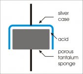
Russian military AgTa cap has quite different construction (without plates) than other ordinary caps - (your favorite) polyprops, electrolytics, etc.
construction of AgTa caps, K52; 53; 3TO, etc. :
see image
peculiarity of construction explains why these caps are too fast and linear...
where to buy?:
click (russian)
Caps 3TO-1;2 are old production of K52-2 type and has different (a little bit bigger than K52-2) geometric dimensions.
see image
peculiarity of construction explains why these caps are too fast and linear...
where to buy?:
click (russian)
Caps 3TO-1;2 are old production of K52-2 type and has different (a little bit bigger than K52-2) geometric dimensions.
An externally hosted image should be here but it was not working when we last tested it.
An externally hosted image should be here but it was not working when we last tested it.
Attachments


Daniel,
Very nice work, a pretty amplifier (any underneath pics?). I've heard that some of the new manufacture 2A3 tubes are the same construction as some of the new manufacture (aka, NOT Western Electric) 300B tubes from the same vendor, albeit with a 2.5 volt filament. Running any NOS 2A3 tubes at the high plate dissipation would surely result in glowing plates and very short life.
One comment on the series-stacked coupling caps. Regardless of how well constructed they are, you still have no means to equally distribute the voltage charge across the group. As they age, the weakest will eventually have an over-voltage condition. Just not sure what the overall result will be.
Any measured specifications for the amplifier?
Regards, KM
kmaier said:Running any NOS 2A3 tubes at the high plate dissipation would surely result in glowing plates and very short life.
I made few SE amps with 6S4S, dual plate triode, the same as 6B4G, wich has anode dissipation (in this case) more than 23 Watts, and there is no problem with them for more than 2 years.
Actually regime is: Usupp=420V (Ua-c=340V, Ia=66-70mA
Anode is totally dark
kmaier said:One comment on the series-stacked coupling caps. Regardless of how well constructed they are, you still have no means to equally distribute the voltage charge across the group. As they age, the weakest will eventually have an over-voltage condition. Just not sure what the overall result will be.
Tantalum (with silver cathode case) caps K52-2 are russian military made and in this case is not necessary to use resistors to align the tension for each cap.
Thanks for the tip on the 6S4S; the Russian datasheet ratings are
so conservative, you never know where the limits are... I just got
a pair to try out.
I never thought of using wet tantalum caps for coupling, but I
guess the small amount of leakage in the 1-2 uA range distributes
the DC voltage. I know they're hell of expensive to buy new (oops
shouldn't have said that...) but they are a totally different animal
from the solid tantalum caps that have such a bad rep sonically and otherwise. They don't have many disadvantages but I suppose you
could overheat them and dry them out. And wet silver-tantalums are
even more special.
I like the wheelhouse transformer cover!
Cheers,
Michael
- Status
- This old topic is closed. If you want to reopen this topic, contact a moderator using the "Report Post" button.
- Home
- Amplifiers
- Tubes / Valves
- 2A3 SE Amp