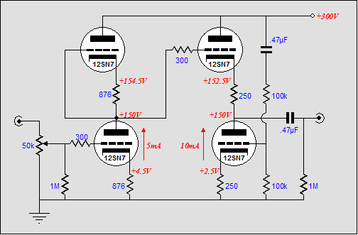
...it's a good new idea!
please check this project if can works (i will try next WE)
http://www.esafono.it/OCNamp.jpg
i have try this and the sound is OK
http://www.esafono.it/perfect.jpg
theory:
http://www.esafono.it/perfect2.jpg
thanks for your attention
Stefano from Milano - Italia
please check this project if can works (i will try next WE)
http://www.esafono.it/OCNamp.jpg
i have try this and the sound is OK
http://www.esafono.it/perfect.jpg
theory:
http://www.esafono.it/perfect2.jpg
thanks for your attention
Stefano from Milano - Italia
The OCN amp circuit as drawn will not work. From a practical point of view the grids are not biased, but that is easily fixed with a resistor from grid to the bottom end of the cathode resistor. But the main problem, and the way the OCN circuit differs from the other circuits shown, is that the grids of both tubes are swinging in the same direction. Both tube currents will increase and decrease at the same time, essentially they are in series conducting one current.
If you want to get some real output, you need to drive the two grids with a regular phase splitter. Then the tubes operate in a push pull fashion, and the current is forced to flow through the load resistor. You can then get a voltage gain of about 1.5 or so out of 12AU7s with +/- 250 volts power supplies, 10K cathode resistors and 100K load. At least that is what I get with a quick SPICE simulation. As drawn the ciruit only puts out 20 mV for 1V in.
For the multistage version shown, with 12AU7, 5814A and 6C33, it makes no sense to gang together stages of this type since they have little or no voltage gain, even if you did drive them correctly with a phase splitter. So what you want instead is a voltage gain stage ie triode connected in the usual common cathode way feeding a phase splitter of what ever type you like best, driving the grids of the paralleled 6C33s.
OCN AMP MKII
Thanks at all
so to have :
a correct phase drive
+ voltage gain
+ central IN/OUT
I try this II solution from Aikido AMP:
http://www.esafono.it/OCNamp2.gif

do you think is a good chain?
Thanks at all
so to have :
a correct phase drive
+ voltage gain
+ central IN/OUT
I try this II solution from Aikido AMP:
http://www.esafono.it/OCNamp2.gif
do you think is a good chain?
other two experiment
http://www.esafono.it/allpushpull.jpg
and reversal mode
http://www.esafono.it/allpushpullreversal.jpg
http://www.esafono.it/allpushpull.jpg
and reversal mode
http://www.esafono.it/allpushpullreversal.jpg
- Status
- This old topic is closed. If you want to reopen this topic, contact a moderator using the "Report Post" button.
