Guys,
Can ya please check out this 813SE design ? Im about ready to get underway; and Im not second guessing my op point for the 813...
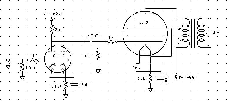
I have the B+ coming out of the PSU @ 900v, and 100mA on the plate. I know this tube can be pushed WAY harder; but would there be any benefit ? My OPT's can take up to 1.2kV/50w
Thanks !
Steve
Can ya please check out this 813SE design ? Im about ready to get underway; and Im not second guessing my op point for the 813...
I have the B+ coming out of the PSU @ 900v, and 100mA on the plate. I know this tube can be pushed WAY harder; but would there be any benefit ? My OPT's can take up to 1.2kV/50w
Thanks !
Steve
Steve,
Harder perhaps, but not "way" harder. I can't find any charts on this for Class A operation. Maybe you should bias it for class C? 900 volts and 100ma on the plate is gonna run the dissipation up pretty good!
It's gonna get warm! But I DO want to hear it when you get it "cookin"! ---ART---
Harder perhaps, but not "way" harder. I can't find any charts on this for Class A operation. Maybe you should bias it for class C?
900 volts and 100ma on the plate is gonna run the dissipation up pretty good!It's gonna get warm! But I DO want to hear it when you get it "cookin"! ---ART---
A couple of points.
First, if you are using AC for the 813's filament then do include a humbucker pot - I fould these very useful and my 813 project was a p-p amplifier.
Second, how much current are you running throught the paralleled 6SN7? There will need to be quite a bit. I would prefer (no doubt it's stereo?) to run the second 6SN7 as a cathode follower; this would drive the 813 much better.
900V and 100mA is an excellent operating point for an 813. I experimented with UL without feedback and the sound was very poor (high anode resistance) Depending on the primary impedance of your transformer, you might well prefer it as a triode - it makes a very good triode indeed,
7N7
7N7 said:
Depending on the primary impedance of your transformer, you might well prefer it as a triode - it makes a very good triode indeed,
7N7
I do agree. DC filaments are mandatory. In my amp the 813 was triode strapped (thanks for the curves) and running at 900V/100mA (fixed bias) with a 10K load (well... it was parafed) for +20W. I would not go with lower loads, but that is my personal take.
Ciao
Gianluca
813 mullings
Steve...
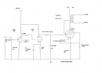
Cool schemo...Hadn't thought of paralleling like that!
Where did you find your OPT? My design is a bit different & I have found all my TXs' off the shelve but not the OPTs'.
Take a look!.........
_____________________________________Rick...........
Steve...
Cool schemo...Hadn't thought of paralleling like that!
Where did you find your OPT? My design is a bit different & I have found all my TXs' off the shelve but not the OPTs'.
Take a look!.........
_____________________________________Rick...........
Attachments
Gents,
Thanks for all the input !
I will be using a tentlabs fil supply; so it'll be regulated DC on the heater. I didn't give much thought into a CF; I paralleled the 6SN7's to get some more current into the 813....Maybe a 2nd tube for the CF that I will just split between the two channels ?
My OPT was custom ordered from Heyboer; very reasonable price. I had it built to be 6K, 40% UL tap, 50w, and voltage up to 1.2kV.
Any suggestions for a feedback circuit ? I would be interested in hearing some ideas...
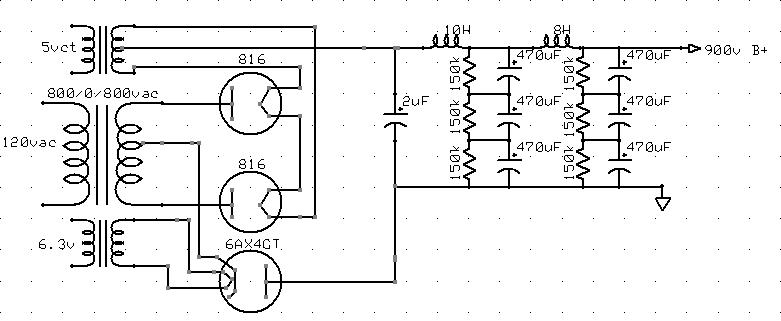
Richard - looks pretty cool - What does your PSU look like ? Here's my idea for my 900v B+
Thanks !
Steve
Thanks for all the input !
I will be using a tentlabs fil supply; so it'll be regulated DC on the heater. I didn't give much thought into a CF; I paralleled the 6SN7's to get some more current into the 813....Maybe a 2nd tube for the CF that I will just split between the two channels ?
My OPT was custom ordered from Heyboer; very reasonable price. I had it built to be 6K, 40% UL tap, 50w, and voltage up to 1.2kV.
Any suggestions for a feedback circuit ? I would be interested in hearing some ideas...
Richard - looks pretty cool - What does your PSU look like ? Here's my idea for my 900v B+
Thanks !
Steve
Steven-H said:Gents,
[...]I paralleled the 6SN7's to get some more current into the 813....Maybe a 2nd tube for the CF that I will just split between the two channels ?
My OPT was custom ordered from Heyboer; very reasonable price. I had it built to be 6K, 40% UL tap, 50w, and voltage up to 1.2kV.
[...]
Steve
Yes, that was my idea; you should use a second 6SN7 for the cathode followers as of course you would have to elevate the heaters to prevent challenges to the heater/cathode insulation.
At your operating point 6k would probably give good results with 813 triode-strapped (Ra = 1.8k).
No suggestions for feedback, I cannot do the maths!
7N7
7N7 said:
Yes, that was my idea; you should use a second 6SN7 for the cathode followers as of course you would have to elevate the heaters to prevent challenges to the heater/cathode insulation.
At your operating point 6k would probably give good results with 813 triode-strapped (Ra = 1.8k).
No suggestions for feedback, I cannot do the maths!
7N7
Thanks !
Im out of my league a bit when it comes to your suggestion to 'elevate the heaters'. What does this mean exactly ?
I'll see if I can find some triode curves; I do want to at least try it in UL first though
Also, later this evening I'll see if I can rework the schematic a bit to include a CF and see what I can come up with for a NFB circuit...
Thanks again !
Steve
Steven-H said:
Thanks !
Im out of my league a bit when it comes to your suggestion to 'elevate the heaters'. What does this mean exactly ?
I'll see if I can find some triode curves; I do want to at least try it in UL first though
Also, later this evening I'll see if I can rework the schematic a bit to include a CF and see what I can come up with for a NFB circuit...
Thanks again !
Steve
Re Heaters:
Every valve has its heater/cathode insulation limits specified in terms of the maximum voltage between the two.
In most amplifiers, the heater supply is referenced to ground, so a typical supply is 3.15-0-3.15v giving 6.3v; the centre tap is connected to ground. A better practice is to attach the centre tap to say +40V, this in the words of Morgan Jones in his book "Valve Amplifiers" "turns off the 'diode'" that is created by the heater filament and the cathode of the valve. This is fine for valves that are running with their cathodes at around 0V. A cathode follower necessarily (unless the cathode is returned to a negative supply) has its cathode at perhaps 200V. In such a case the centre tap of the heater supply should be referenced to at least 200V. This is fully covered in "Valve Amplifiers".
As for triode curves, I have a set; these my be found on Pete Millet's site - I am not at home at present so cannot send them to you.
7N7
Steven-H said:I see.....
So I understand the theory - but in practice what you are saying is that I should toss a resistor or voltage divider off of my 400v B+ line, and hook the CT of the 6.3v line to it ?
Thanks again,
Steve
Yes, that would work but there is a better way of doing this than using a potential divider; again see "Valve Amplifiers". Jones has devised a circuit that he calls the THINGY, this provides a suitable DC supply with low output resistance.
7N7
Steven-H said:I see. So I Imagine 60k would be a good place to be ? I guess my concern there is that I figured I was being border-line on the 6SN7 B+ @ 400v...
Well you wouldn't be swinging that much.
Note that 6SN7 and 7N7 have Va max at 300V; 6SN7GTA/B are limited to 450V Va. I have never seen a limit specified for the HT supply.
As RDF says, better to have a larger anode load; this will reduce distortion too. If you have cathode followers, drive will not be a problem. As a triode at your operating point your bias voltage will be around -85 - -90V; 813 is easy to drive.
7N7
Ok - So...
I have the tube bias set @ -8v; at which it will pull about 6.5mA.
Using V=IR, then V= .006*33000, and V = 214.5
So, the voltage seen on the plate is (B+)-V, or 185.5v.
If I want to increase R to say...60k, then I would have:
V=.0065*60000, then V=390v.
Therefore, 185.5= x - 390v, or B+ would have to equal about 575v
Look correct ?
- Status
- This old topic is closed. If you want to reopen this topic, contact a moderator using the "Report Post" button.
- Home
- Amplifiers
- Tubes / Valves
- 813 Thoughts