In this circuit the input pentodes run in a sort of triode mode. The screen is not connected to the plate but the screen voltage will follow the plate voltage due to feedback from the primary side of the output transformers. If the fraction fed back is equal to 1/A, where A is the amplification of the output stage, then the screen voltage will follow the plate, just as in triode operation.
So, when extending the screen-anode loop to include the output stage there will be local feedback, in this case about 4:1 or 12dB which will reduce the output resistance of the output tubes by a factor of rp/(1+(B*mu)). That indicates that the global feedback could be kept low, like 6dB as in this prototype.
Anyone tried this feedback scheme? Any pitfalls?
What I could think of is that the input pentodes will lose some gm compared with a true triode connection. Compensation might be to choose a pentode with higher gm in the first place.
Jan E Veiset
So, when extending the screen-anode loop to include the output stage there will be local feedback, in this case about 4:1 or 12dB which will reduce the output resistance of the output tubes by a factor of rp/(1+(B*mu)). That indicates that the global feedback could be kept low, like 6dB as in this prototype.
An externally hosted image should be here but it was not working when we last tested it.
Anyone tried this feedback scheme? Any pitfalls?
What I could think of is that the input pentodes will lose some gm compared with a true triode connection. Compensation might be to choose a pentode with higher gm in the first place.
Jan E Veiset
question about output transformer screen taps
A question about the output transformer : I am interpreting the
6k8/2+2R to indicate 6800 ohms plate to plate primary, and 2 secondary windings, 2 ohms each ( = 8 ohms overall ). But what about the screen taps ? Are they at the typical 40 % voltage point, or something else ?
Also perhaps a silly question, but if the net effect is to have screen voltage follow plate voltage, and thus act as a triode, why not just wire the pentode as a triode ?
Robert McLean said:Are they at the typical 40 % voltage point, or something else ?
40 % sounds good to me. 🙂
Robert McLean said:why not just wire the pentode as a triode ?
I would miss the feedback loop. (plate {input pentode} -> grid {output pentode} -> plate {opposite output pentode (magnetic coupling)} -> screen grid {input pentode}).
Jan E Veiset
Interesting design Jan. The screen feedback loops will now have more gain to correct the outputs than regular UL mode.
1st, a question. Is the output stage running in class AB? If so, then when one side cuts off, your feedback loop has to operate thru the output xfmr, raising concerns of phase shift in the loop.
Standard UL mode at least has tube drive thru the winding side that is actively feeding back.
Connecting the screen feedbacks down to the cathodes instead would fix the cross coupling problem.
Another fix for cross coupling, which I have not seen used, is to put class AB totem pole drives (ie, two outputs per side and one of them to a double B+) on each side of the primary, that way both sides of the xfmr are always driven.
The other concern I would have is the screen current drawn by the EF86s. If it is nearly constant, then fine. But with much variation (and you have the screens shown at 150V, same as the plates, where it will vary max.), could lead to loop non-linearity. In which case a Mosfet follower screen drive would seem called for, or lowering the DC screen voltages by using the attenuators to ground solely, rather than the 56K differential attenuator.
Hope I didn't put a show stopper in the way, but those are things I would keep in mind.
Don
smoking-amp said:1st, a question. Is the output stage running in class AB? If so, then when one side cuts off, your feedback loop has to operate thru the output xfmr, raising concerns of phase shift in the loop.
Standard UL mode at least has tube drive thru the winding side that is actively feeding back.
Connecting the screen feedbacks down to the cathodes instead would fix the cross coupling problem.
I rely on magnetic coupling between the push and pull side. That might or might not be a good idea, anyway that will depend on the transformers and I am not sure about the result. Time will show?
smoking-amp said:The other concern I would have is the screen current drawn by the EF86s. If it is nearly constant, then fine. But with much variation (and you have the screens shown at 150V, same as the plates, where it will vary max.), could lead to loop non-linearity.
That is a real concern, yes! And that is the reason why I have not chosen a high gm pentode for the input stage in the first place. Higher gm, higher g2 current, etc, etc..
smoking-amp said:Hope I didn't put a show stopper in the way, but those are things I would keep in mind.
No you didn’t, I am glad that someone took the trouble to look into the design. 🙂
Jan E Veiset
I have tried to do some calculations (with a lot of assumptions):
If we assume that Ig2 =~10% of Ia and that Ia is swinging between 2.5 and 3.5mA (50Vpp) then Ig2 will swing between 0.25 and 0.35mA. The equivalent source resistance of the feedback network is ~15k; this means that the screen voltage will vary +23.75/-24.5V (with +/-50V feedback) which will result in 2nd harmonic, about 1.5%. As far as I can see this 2nd harmonic is opposite of the 2nd harmonic of the tube which indicates that the total 2nd harmonic will be lower.
In a symmetrical push pull stage, much of this distortion will be cancelled, but there will be remaining odd harmonics. The global 6dB feedback loop will in the end halve this distortion.
There will of course be many sorts of non-linearity in the tubes too, so all in all the picture is more complex. But the feedback arrangement doesn’t look that bad?
Jan E Veiset
Hi Jan,
It just sank in here that the driver screens are tracking the plates near exactly (as you said), so the screen current stays at a constant fraction of plate current. (as you calculated) This is an unexpectedly neat result. So driver screen current distortion should not be a big concern.
On the cross-coupling loop thru the xfmr phase concern, I have been thinking. If the feedback loops do not draw any current from the undriven primary side (class AB), then no voltage drop occurs across the xfmr leakage inductance from the other driven primary side.
So putting a Mosfet follower between the primary and the feedback network should alleviate this problem in class AB. Without the Mosfet buffer, there is Rfeedback network & Lxfmr leakage giving a low pass function. If you can determine where it falls in frequency, you could determine how necessary the buffer is. With the 100K feedback resistors shown, maybe the buffers are unnecessary.
Don

Hi Jan,
Any results on this design yet?
I was thinking recently about a local feedback scheme and thought it might be useful for your circuit as well.
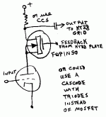
By using a cascode gain stage instead of the EF86 stage, the input impedance of the "screen" can be much higher. This would eliminate any concern of phase shift due to the cross-coupled feedback going thru the output xfmr in class AB. (no current -> no phase shift thru xfmr leakage inductance)
A low capacitance Mosfet could be used as well for the top section of the cascode for simplicity.
A pair of CCS's could also be tried for the top section "plate" loads to put high gain in the local feedback loop. This would likely need some careful frequency rolloff network somewhere to maintain loop stability.
Don
Any results on this design yet?
I was thinking recently about a local feedback scheme and thought it might be useful for your circuit as well.
By using a cascode gain stage instead of the EF86 stage, the input impedance of the "screen" can be much higher. This would eliminate any concern of phase shift due to the cross-coupled feedback going thru the output xfmr in class AB. (no current -> no phase shift thru xfmr leakage inductance)
A low capacitance Mosfet could be used as well for the top section of the cascode for simplicity.
A pair of CCS's could also be tried for the top section "plate" loads to put high gain in the local feedback loop. This would likely need some careful frequency rolloff network somewhere to maintain loop stability.
Don
Attachments
No progress yet, I’m waiting for parts. The lead time for the OPTs is 4 weeks plus shipping and customs clearance.
The leakage between the primary sides of the OPT is not specified, but L Leak prim ref secondary is 4.4mH. The transformer is according to Sowter well suited for feedback circuits (no major resonance issues etc).
If we look at L leak (prim/prim) and the load (screen grid feedback) as a low pass filter, we know the load. The load is greater than 100k and if the bandwidth target for the feedback loop is 50kHz L leak must not exceed L=R/(2Pi f)=~300mH.
Before I have measured the prim/prim leak I can’t tell if I’ll need a Mosfet buffer or not.
Anyway, with three feedback loops, each of them could be kept relatively modest, and each of them will contribute to the amplifiers sonic signature in different ways. The ultra linear feedback is of course fixed but the other feedback loops are subjects for tweaking, and Mosfets could be a part of that.
Thanks for your interest Don. 🙂
Jan E Veiset
- Status
- Not open for further replies.
- Home
- Amplifiers
- Tubes / Valves
- Feedback scheme.