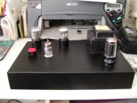

Its functional but does have a slight hum even after the pot was added. Like I said this was made on a budget with most parts being used. It won't take any beauty contests but I tend to like the performance. Many thanks for my questions that have been answered with patience and the help.
Joe
Joe
Re: HUM.
Yeah. Frank is probably right.
fdegrove said:It sounds like you have a groundloop somewhere.
Yeah. Frank is probably right.
Mistake
I made a goof. I'm so used to using a butt set to trouble shoot audio that I forgot its not capable of going very low in frequency.
Yes, I have hum on the output of the pre amp.
The following voltages were taken at the tubes
12AY7
pin 1 120v, pin3 1.9volt pin
6SN7
pin 1 66volt, pin2 243volt pin3 85v
the voltages were taken with respect to ground with zero signal and input unshorted.
any ideas?
Joe
Re: Mistake
This is a problem. You have the 6SN7's biased at -19V at idle. Quite obviously you've made a wiring error.
burnedfingers said:6SN7
pin 1 66volt, pin2 243volt pin3 85v
This is a problem. You have the 6SN7's biased at -19V at idle. Quite obviously you've made a wiring error.
burnedfingers said:I checked the values and placement of the parts and they are correct with your schematic.
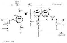
Joe, please check again with this schematic. There is no way a 470 ohm resistor is going to produce 19V of bias. Something is wired wrong, and I suspect it's the junction of the 470, 7.7k, and 470k resistors.
Attachments
Joel
If you substitute a 47K resistor for the 470K value it will bring the voltages to 80 on pin 1 and 87 on pin3 with a supply voltage of 244 volts. If you raise the supply voltage to 284 it will raise the pin1 voltage to 93v and pin3 to 102. Is it possible that the 470K value should have been 47K? Are these operating voltages in line with what a 6SN7 should run? Did I kill my tubes by running too much bias? Help me here someone?
Joe
burnedfingers said:Is it possible that the 470K value should have been 47K? Are these operating voltages in line with what a 6SN7 should run? Did I kill my tubes by running too much bias? Help me here someone?
1) No, it should not be 47k. 470k is correct. The reason the voltages change when you lower this value is you're making the grid more and more at the same potential as the cathode. You can see where this will lead by shorting the grid to cathode - what is the voltage at both? Why, the same, of course.
2) A 6SN7 can take 400V, so this is nothing to worry about. As close to 250V as you can get it is good in this circuit. Also, note the bias voltages increase when you increase the plate voltage because the current is dropping.
3) You can't "kill your tubes" by overbiasing - that turns them off. You can kill your tubes by UNDERbiasing - that increases current.
Without having it in front of me, it's hard to understand why we're having so much trouble here - but just get the B+ at 250V, and then play with the bias resistor value (470 ohm) until you get a differential of 8V between grid and cathode. Leave all the other values the way they are. Ok?
What voltages should I see?
Since you want me to keep the 470K and the 7.7 values and fudge the 470 Ohm value, what voltage should I see at the cathode and the grid with a given 250 volt plate voltage?
Just making a guess here... since you don't want me to change the 470K value there must be a ballpark level you want to see on the cathode and I must have violated it. It seems to me that changing the 470K to 47K raised the cathode voltage by 2volts and brought the grid voltage more in line with what you wanted me to have.
I'm going to find a very large beer to inhale.
Joe
PREAMP.
Hi,
Just measure the voltage between grid and cathode at the socket Joe.
Cheers,
Hi,
Since you want me to keep the 470K and the 7.7 values and fudge the 470 Ohm value, what voltage should I see at the cathode and the grid with a given 250 volt plate voltage?
Just measure the voltage between grid and cathode at the socket Joe.
Cheers,
Ok, with a rail of around 290volts the 470 Ohm value needs to be aprox 1.065K in order to bias at 8volts. What kind of voltage with respect to ground am I supposed to see on the cathode and grid?
What do I need for bias on the 12AY7? I have 1.2volts from grid to cathode.
Joe
What do I need for bias on the 12AY7? I have 1.2volts from grid to cathode.
Joe
JOEL?
Hi,
From the grid to ground you wouldn't measure anything, between grid (pin 1) and cathode (pin 3) you should measure minus ! 8 volts with a ~ 250VDC B+.
Should be - 4 VDC under the same circumstances as above.
Why don't you drop the excess 40 V in the PSU with a resistor ?
Cheers,
Hi,
What kind of voltage with respect to ground am I supposed to see on the cathode and grid?
From the grid to ground you wouldn't measure anything, between grid (pin 1) and cathode (pin 3) you should measure minus ! 8 volts with a ~ 250VDC B+.
What do I need for bias on the 12AY7? I have 1.2volts from grid to cathode.
Should be - 4 VDC under the same circumstances as above.
Why don't you drop the excess 40 V in the PSU with a resistor ?
Cheers,
- Status
- This old topic is closed. If you want to reopen this topic, contact a moderator using the "Report Post" button.
- Home
- Amplifiers
- Tubes / Valves
- Joel's 6SN7 preamp (photo)