I have a pair of 5K:8 push pull OPTs, and I am wondering if people have output tube recommendations for them. I think they were probably designed with 2a3's in mind, but I am too cheap to buy 4 of those. I thought about running them 20K:32 as a headphone amp with 6H30's, but it seems like a silly use, and I could frankly use a real power amp for once. Maybe 6AS7's? Any better ideas?
Hi Dsavitsk
If you are going for the cheap tubes I would recommend you give a look at the sweep tubes (horizontal deflection in TV sets, if I am right). There have been several threads discussing amps with those, including a recent thread by Miles Prower using the 6BQ6GTB.
http://www.diyaudio.com/forums/showthread.php?s=&threadid=105724&highlight=6bq6
He is using a 4k4 P2P OPT, so 5k should be fine as well.
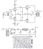
These tubes find different uses: some triode them and use them low and hot (because G2 is generally rated for values up to 200VDC). Other (as Miles) use them in penthode mode, where one can keep G2 under the max.value. Still others use to apply the signal straight to a slightly negative biased G2, having both G1 and G3 grounded, aiming for a very linear class B operation (SY is an example). Download a good datasheet of a 6JN6 and look at the curves for G1 grounded (=0). THe curves are for the values of G2, in the left axis you will see the current draw through the plate, on the right (generally) the current drawn by G2. As you see the signal must be quite 'healthy': large amplitude fed from a low output source (cathode follower). www.davidberning.com has built several amplifiers with this configuration. Still other (Tubelab) do something similar, but bias G1 slightly negative, keeping G2 positive. The advantage of the last two circuits are large power with low dissipation in the tube, assuring a longer lifetime. In one of Berning's amplifiers he is even using only 5.7VAC on the 6.3V filaments of the 6JN6.
You see, lots of applications for those chaep tubes, and I have not seen anyone complaining of sound quality in any of the above mentioned configurations. I have not built any of them (yet), but that will come about after finishing other projects: I already collected a stash of 25DQ6B's and 22JF6's (not the everyday tubes, diyaudio search would probably not bring up much results).
Still, the 6AS7 sounds as a good idea to! Shoog has built a quite simple, completely differential, two stage, amplifier with them, with apparently quite good results.
Erik
If you are going for the cheap tubes I would recommend you give a look at the sweep tubes (horizontal deflection in TV sets, if I am right). There have been several threads discussing amps with those, including a recent thread by Miles Prower using the 6BQ6GTB.
http://www.diyaudio.com/forums/showthread.php?s=&threadid=105724&highlight=6bq6
He is using a 4k4 P2P OPT, so 5k should be fine as well.
These tubes find different uses: some triode them and use them low and hot (because G2 is generally rated for values up to 200VDC). Other (as Miles) use them in penthode mode, where one can keep G2 under the max.value. Still others use to apply the signal straight to a slightly negative biased G2, having both G1 and G3 grounded, aiming for a very linear class B operation (SY is an example). Download a good datasheet of a 6JN6 and look at the curves for G1 grounded (=0). THe curves are for the values of G2, in the left axis you will see the current draw through the plate, on the right (generally) the current drawn by G2. As you see the signal must be quite 'healthy': large amplitude fed from a low output source (cathode follower). www.davidberning.com has built several amplifiers with this configuration. Still other (Tubelab) do something similar, but bias G1 slightly negative, keeping G2 positive. The advantage of the last two circuits are large power with low dissipation in the tube, assuring a longer lifetime. In one of Berning's amplifiers he is even using only 5.7VAC on the 6.3V filaments of the 6JN6.
You see, lots of applications for those chaep tubes, and I have not seen anyone complaining of sound quality in any of the above mentioned configurations. I have not built any of them (yet), but that will come about after finishing other projects: I already collected a stash of 25DQ6B's and 22JF6's (not the everyday tubes, diyaudio search would probably not bring up much results).
Still, the 6AS7 sounds as a good idea to! Shoog has built a quite simple, completely differential, two stage, amplifier with them, with apparently quite good results.
Erik
Yes, you are right Geek. When I was talking about shoog's amplifier I had already forgotten the 5k figure. Still, the 'maurits' amplifier by van der Veen uses a 8k P2P trafo as output tranny. I remember asking about the amplifier here at diyaudio and, I think it was positron, recomending to stay faaaaaaaaar away from it.
Erik
Erik
Thanks for the ideas.
This looks really interesting, and looks like there is lots for me to learn as well. Plus, I have a few boxes of 12AU7's, 6sn7's, and 12AT7's that might get put to some good use here.
There is a possibility that this could end up being used with some 4 ohm speakers. Maybe it's more reasonable there?
Seems too easy, and EL34's still aren't quite free. But, maybe worth a look.
ErikdeBest said:recent thread by Miles Prower using the 6BQ6GTB.
This looks really interesting, and looks like there is lots for me to learn as well. Plus, I have a few boxes of 12AU7's, 6sn7's, and 12AT7's that might get put to some good use here.
Geek said:5K is way too high for a 6AS7.
There is a possibility that this could end up being used with some 4 ohm speakers. Maybe it's more reasonable there?
ray_moth said:5k P-P is an ideal load for EL34s in triode-mode AB1 PP with 400v plate-cathode voltage. If you want to use cathode resistor or CCS bias, you need about 440v B+.
Seems too easy, and EL34's still aren't quite free. But, maybe worth a look.
Hi,
I think they loadline around 1.3K. So parallel 4 ohm speakers.... dipole, bipole, whatever they're called")
dsavitsk said:There is a possibility that this could end up being used with some 4 ohm speakers. Maybe it's more reasonable there?
I think they loadline around 1.3K. So parallel 4 ohm speakers.... dipole, bipole, whatever they're called
What about the 6AQ5?
This was the tube that was substituted for a 6B4G, and gas a couple of threads going. Last I looked, they were $4 each.
As for the 6AS7, having a higher Primary that normal gives lower power and better distortion. The question you need to ask is: Can you live with a quarter of the normal power? If you can, its a perfect fit.
Good Luck,
Doug
Still, the 6AS7 sounds as a good idea to! Shoog has built a quite simple, completely differential, two stage, amplifier with them, with apparently quite good results.
In my 6080 PP amp I am using mains toroidals for the outputs, I took some 18V+18V:120+120 which I unwound the secondaries to 6V. I run them with the secondaries in parallel with 4Ohm speakers for a nominal impedance of 6,400Ohm. I have tried them with the secondaries in parallel, and the output falls off massively and the signal distorts badly, thats with the impedance at 1,600ohm - which should theoretically be spot on for the design. I really don't know whats going on with this, possibly my memory fails me and I didn't unwind them in the way I thought. But on the basis of that a simple PP 6080 with 5K outputs might work well.
Shoog
Back to revisiting this. I drew up a possible schematic -- basically trying to use as many parts as I have on hand. I think the only thing I need to buy are a pair of power transformers. These will be monoblocks.
Anyone have any thoughts about the wisdom of the design? The choke is rated at 120mA, so the 6080 runs at 55mA per side and the 6N1p is at 5mA per side.
Anyone have any thoughts about the wisdom of the design? The choke is rated at 120mA, so the 6080 runs at 55mA per side and the 6N1p is at 5mA per side.
Attachments
Shoog said:You need a a means of current balancing.
How important is this? Is a reasonably matched tube not going to be enough? The transformer could certainly have a cap inserted and be used with a pair of CCSes as a parafeed design. But, most push-pull schematics I've looked at that use this output stage don't seem to worry about this beyond matching tubes:
http://www.electra-print.com/docs/6bx7pp0001.pdf
http://nutshellhifi.com/Amp-pix.gif
Shoog said:What driver voltage are you expecting.
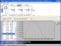
I'm not exactly clear on how to do this calculation in PP -- I've only ever really worked with single ended designs. But, I figure that the 6N1p can take 2V p-p at each side (it is biased up 1V), and that will be just shy of a 60V swing on the grid of the 6080, which is about where the 6080 will clip. There should be about 110V on the plate of the 6N1p which means that the CCS will clip right before the tube depending on how efficient it is. I'm not sure how this translates into push-pull, however.
Shoog said:Are you thinking of those Lundahls for the front end?
That's the plan. I had forgotten all about this project, and then had my memory jogged that I had these OPTs in a drawer.
Hi Dsavitsk
From own experience I can say that the two triodes of the 6080 are hard to get matched, and the single resistor in your schematic is about the worst auto-bias method there is
Broskie's explanation
Erik
From own experience I can say that the two triodes of the 6080 are hard to get matched, and the single resistor in your schematic is about the worst auto-bias method there is
Broskie's explanation
Erik
Sounds as if your about right on your driver calculations.
Unfortunately the two sides of a 6080 are notoriously badly matched - they never really needed to be in their intended role. I have used a suggestion of Brian Becks whereby I have LM317 CCS's in the tails of each triode. This takes care of current balance. I then have two large caps between the cathodes which effectively turns the pair differential. The cathodes of the caps are tied and referenced to earth via a 1meg resistor to keep them biased.
This has worked really well for me, and they have stayed in perfect balance until such time as they drift to badly and then they start to oscillate. Simple, differential and adjustment free - what more could you ask for.
Shoog
ErikdeBest said:Hi Dsavitsk
From own experience I can say that the two triodes of the 6080 are hard to get matched, and the single resistor in your schematic is about the worst auto-bias method there is
Broskie's explanation
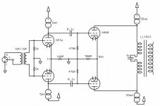
The problem for me is that I am really cap phobic -- pathologically so. I will go to silly lengths to get caps out of the signal path, and Broskie, unfortunately, does not share this particular pathology. I have a pretty good stash of 6080's, but assuming I can't find one with reasonably matched sides, I'd almost prefer to do something like the attached. The bias resistor in this case works more or less like fixed bias with the signal current not going through it. My DAC and preamp both use a version of this circuit, so my experience is that it works reasonably well.
There is also an added benefit that I need not drop so much voltage in the power supply, or get it so clean, and can thus use a different driver (if it comes to it) that wants a bit more on the plate -- 12at7 or something. For the added cost of more CCSes, I'll save on PS caps.
Edit: though I guess the down side is limited swing on the output stage -- might be a problem.
Shoog said:I have used a suggestion of Brian Becks whereby I have LM317 CCS's in the tails of each triode. This takes care of current balance. I then have two large caps between the cathodes which effectively turns the pair differential. The cathodes of the caps are tied and referenced to earth via a 1meg resistor to keep them biased.
This has worked really well for me, and they have stayed in perfect balance until such time as they drift to badly and then they start to oscillate. Simple, differential and adjustment free - what more could you ask for.
Do you have a link to a schematic? Sounds interesting.
Attachments
- Status
- This old topic is closed. If you want to reopen this topic, contact a moderator using the "Report Post" button.
- Home
- Amplifiers
- Tubes / Valves
- Use for 5K:8 PP OPT?