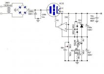
designed and tested the power supply shown below. Its a 100-300V regulated power supply capable of providing about 700mA according to Vout. The hum component is about 2mV at 700mA for rated output (100-300V). Good thing about it is that it is virtualy indestructable. I mean even if you accidentaly shortcircuit the output the pass element tube shuts down and no harm is done.
What I would like to ask is if it is possible to use instead of 6AU6 pentode and reference a better comparison device as an OP-AMP where we can benefit from extra gain available. As I am not much into solid state I would like to ask how is it possible to be done. Note that in order to achive the needed voltage adgustment, voltage between cathode and grid of the tube should be about -40V to -90V with respect to the cathode.
Any Ideas, help?
Attachments
No need for a high voltage op-amp per se, but then you need a driver stage for the tube pass element. The tricky thing with pass tubes is low mu, so quite a lot of drive is needed to turn them off. One thing which is useful, is a floating low voltage supply for the op-amp, makes things much easyer.
A symetrical supply makes it easyer for the Opamp, it's ground is referenced to the output of the regulator. To be honest, it's a 'bit' complicated to do with a ube as the pass element (many supplies needed, heater, HV drive, op-amp). You could use a single supply for the OPamp as well, but lay out the 'error amp' you use the op-amp for so that a single supply is enough, in whicjh case it will probably be best if it's positive side is referenced to the output of the regulator. Since you are using the cathode of the pass tube as the output, you could use it's heater supply to derive the supply for the OPamp.
U1 -- LR8N3 -- is a part which costs less than $1 -- used in switching supplies to regulate the front end it can be deployed thusly for a fixed voltage. Substitute a potentiometer for R2 and it'll be adjustable:
Of course you can use it with a 6L6 for the pass element if you desire!
I keep a supply of them on my webstore, Mouser carries them as well.
An externally hosted image should be here but it was not working when we last tested it.
Of course you can use it with a 6L6 for the pass element if you desire!
I keep a supply of them on my webstore, Mouser carries them as well.
Allright, it seems that tube pass elements are not so popular. Thus let me unfold my reasoning in using 6C33. It is ment to be used in a stereo amplifier with another two 6C33s as output tubes.
The rectifier gives a 360VDC out and my needs for the amplifier are 240V adjustable (170-260V for testing purposes) with total current demand of about 400mA. Thus if I was opting for a mosfet I would need a heatsink to dissipate about 50W continyously, which is huge. On the other hand I allready have a good transformer with lots of sepparate windings for auxiliary purposes and space to mount the 6C33 pass element. And finally if this works out it can also be replicated for a very robust bench supply. ANy ideas of a HV comparator that I may use? I found LM143 up to the task but it is obsolete. On the other hand, is it possible to setup a common opamp driving a fet of bipolar to extend its output from about 20v to be able to swing about 100 that it is needed for the grid of the tube?
The rectifier gives a 360VDC out and my needs for the amplifier are 240V adjustable (170-260V for testing purposes) with total current demand of about 400mA. Thus if I was opting for a mosfet I would need a heatsink to dissipate about 50W continyously, which is huge. On the other hand I allready have a good transformer with lots of sepparate windings for auxiliary purposes and space to mount the 6C33 pass element. And finally if this works out it can also be replicated for a very robust bench supply. ANy ideas of a HV comparator that I may use? I found LM143 up to the task but it is obsolete. On the other hand, is it possible to setup a common opamp driving a fet of bipolar to extend its output from about 20v to be able to swing about 100 that it is needed for the grid of the tube?
You can use something similar, just replace a trimpot by a pot, and recalculate some values:
http://amfone.net/Amforum/index.php?topic=4842.0
I don't believe that you need better regulation for tubes.
http://amfone.net/Amforum/index.php?topic=4842.0
I don't believe that you need better regulation for tubes.
jackinnj said:Anatoliy -- I am shocked -- the BC348 was the first receiver I ever bought -- it cost about $80 from Fair Radio Sales in Lima OH. I had been using a Knight Star Spanner prior to that.
These were the days when you could get an AN/ART-13 for about $200.
Sorry for off-topic...
I still use mine that I bought for $45 + shipment.
I take IF through a capacitive divider and feed it to a modified AM/FM radio that uses Japanese chip. The AM is hard tuned to 915 KHz (It would be great to find a 1370 KHz crystal, but I still had no chance...).
The set outperformed well serviced Collins R-392/URR that I kept in my bedroom so I sold it on ePay.
panos29 said:
<snipped>
On the other hand, is it possible to setup a common opamp driving a fet of bipolar to extend its output from about 20v to be able to swing about 100 that it is needed for the grid of the tube?
Yes. See the following application notes:
- AN-272 at http://www.national.com ,
and
- AN18 at http://www.linear.com .
I hope that those are helpful.
- Tom Gootee
http://www.fullnet.com/~tomg/index.html
dead end
Thanks everybody for the interest and help. Afer alot of experimentation and one or two dead 741s, I decided that driving the grids of a 6C33 through a tinny opamp is simply impossible, at least considering my knowledge level of SS chips. Thus I am abandoning this project and I will work on my working prototype based on 6AU6 and 5651.
Thanks again,
Panos
Re: dead end
Just reference the opamp to ground and use a high voltage transistor (such as a TIP50) as a common emitter amplifier (with, say, a 470k collector resistor) to drive the series pass tube grid.
The opamp can be configured as an intergrator, with a overly large time constant to ensure stability just to get a prototype working.
panos29 said:Thanks everybody for the interest and help. Afer alot of experimentation and one or two dead 741s, I decided that driving the grids of a 6C33 through a tinny opamp is simply impossible, at least considering my knowledge level of SS chips. Thus I am abandoning this project and I will work on my working prototype based on 6AU6 and 5651.
Thanks again,
Panos
Just reference the opamp to ground and use a high voltage transistor (such as a TIP50) as a common emitter amplifier (with, say, a 470k collector resistor) to drive the series pass tube grid.
The opamp can be configured as an intergrator, with a overly large time constant to ensure stability just to get a prototype working.
Re: dead end
You don't need to kill 741'th, just use one high voltage transistor on output of the opamp, like somebody advised already. Or use a transistor only without any opamp as on the link I've posted.
panos29 said:Thanks everybody for the interest and help. Afer alot of experimentation and one or two dead 741s, I decided that driving the grids of a 6C33 through a tinny opamp is simply impossible, at least considering my knowledge level of SS chips. Thus I am abandoning this project and I will work on my working prototype based on 6AU6 and 5651.
Thanks again,
Panos
You don't need to kill 741'th, just use one high voltage transistor on output of the opamp, like somebody advised already. Or use a transistor only without any opamp as on the link I've posted.
Hybrid Power Supply is done!
After months of experimenting and trial and error I finally managed to arrive at a working prototype. It is based on a new HV opamp made by texas OPA454. The prototype is capable of 1 A, yes 1A at 220V with less than 1,5mV ripple fully loaded, which is more like random noise on my scope. One problem I noticed is that when the speed-up capacitor (68n) is out of the circuit the power suplly is unstable producing a steady 5-6KHz oscillation. Otherwise the circuit is very stable and there is no measurable drop in output voltage from no load to full load.
Any comments or suggestions are very welcome.
Attachments
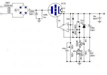
Allright, please disregard the previous schematic, as I made a mistake, the opamp inputs are the other way around. I enclose the corrected schematic with some small changes at the values of the speed up capacitor from 68n to 470n and the output capacitor, from 10u to 68u. These changes are really needed for the correction of the HF frequency responce of the regulator. Any proposals concerning the correction or upgrade of the schematic are very much appreciated.
Attachments
- Status
- This old topic is closed. If you want to reopen this topic, contact a moderator using the "Report Post" button.
- Home
- Amplifiers
- Tubes / Valves
- HV benchtop power supply, help on opamp setup