For example use 6S3PEV with variation of Futterman
set plate votage 140V and plate current 20ma
the internal resist will be 2270 ohm
gain will be 50
the output impedance is Rp/2*(1+gain so for two 6S3PEV this will be ~2270/2*(1+50) = 21.8 ohm.
and with 6 tubes Zo= 21.8/3= 7.2 ohm
but I wander how to calculate the power out?
I'm interest in built OTL
I had some 6528 6528A
they are good for OTL but maybe over heat
so I want to built smaller one
any advise
The output power in class A will be very low, it can be calculated as:
(2 * Ipk)^2 * Rl / 2 = 6 mW for 2 tubes or 54mW for 6 tubes
In class AB you can get much higher output power as the peak current can allowed to be higher, output power in class AB is:
Ipk^2 * Rl/2
As an example: to get 25W in 8 ohm you need peak current of 2.5A which only the 6C33C can get away with.
Regards Hans
@Hans
Hello Hans, how about using an output trans (o.k. no OTL) with low (about 50 Ohm) Primary load? I have made a pair, 120,70,50,16/8 Ohm with 2H pri. Inductance and -3db at 200kHz. Power handling is about 30w/20Hz for 1T induction.
Aim is to get 25-30w with much less current and drive swing.
But i' m a bit confused with the operating point. Should i stay with low voltage/high current ??
Thanks in advance
Konstantinos
tubetvr said:The output power in class A will be very low, it can be calculated as:
(2 * Ipk)^2 * Rl / 2 = 6 mW for 2 tubes or 54mW for 6 tubes
In class AB you can get much higher output power as the peak current can allowed to be higher, output power in class AB is:
Ipk^2 * Rl/2
As an example: to get 25W in 8 ohm you need peak current of 2.5A which only the 6C33C can get away with.
Regards Hans
Hello Hans, how about using an output trans (o.k. no OTL) with low (about 50 Ohm) Primary load? I have made a pair, 120,70,50,16/8 Ohm with 2H pri. Inductance and -3db at 200kHz. Power handling is about 30w/20Hz for 1T induction.
Aim is to get 25-30w with much less current and drive swing.
But i' m a bit confused with the operating point. Should i stay with low voltage/high current ??
Thanks in advance
Konstantinos
But i' m a bit confused with the operating point. Should i stay with low voltage/high current
There is nothing wrong with low voltage, I use +/- 140V in my OTL the problem is the tubes you have chosen they are not suitable for OTL.
A 8 Ohms speaker already needs a few Amperes for higher output which a tube simply cannot deliver.
WRONG! there are at least 2 available tubes that can be used for OTL with good results, either the 6C33C that can deliver in excess of 3A peak with high reliability or EL509 that can deliver 1.5A peak. as an example there is no problem at all to build an OTL with 2 6C33C that can deliver 25W in 8 ohm continuous power and with good reliability.
Regards Hans
I know these Tubes very well and that they can handle high peak currents..I know even some more of them.
I've got a few of the gigantic 7242. They can handle nearly 1A at AVERAGE. But i wouldn't ever consider to use them in an OTL.
But that doesn't change the fact that Tubes are not suitable to operate on a 8 ohm load. Maybe they can handle a few Amperes peak. I can handle 200BPM pulse, too. But not all the time !!
My post above was ment as a good hint. Nothing else
It is much esier und more economic to get the output power using a large voltage delta --> High Z-out --> output transformer as using lots of current to get power out of a tube.
I've got a few of the gigantic 7242. They can handle nearly 1A at AVERAGE. But i wouldn't ever consider to use them in an OTL.
An externally hosted image should be here but it was not working when we last tested it.
But that doesn't change the fact that Tubes are not suitable to operate on a 8 ohm load. Maybe they can handle a few Amperes peak. I can handle 200BPM pulse, too. But not all the time !!
My post above was ment as a good hint. Nothing else
It is much esier und more economic to get the output power using a large voltage delta --> High Z-out --> output transformer as using lots of current to get power out of a tube.
It's me again....
Just tried to figure out this "25W into 8Ohms" amp. Push Pull class B (must be class B, no Tube can handle such quiescent currents)
To get 25W in 8ohms, we will need SQRT(25W/8Ω) ~~ 1,77A continious current.
But we have a sine signal and want the 25W with a sine voltage thus sine current (resistive load, "ideal Loudspeaker")
So the peak current value is 1,77A*SQRT(2) = 2,5A
The tube MUST deliver this 2,5A peak !
At the moment we only know the peak current of the half waves which appear only every second time, cause we're in class B. (graph would look like a half-wave rectifier)
Now it's interesting to know the average value of current which would flow through this tube.
This equivalent if we want to know what continous current causes the same amount of charge going through the tube as our half-wave-sine
So we need to integrate the half sine current over the time and finally divide it by one fixed period (1/T).
The *0,5 is needed because of the half waves and not full waves.
0,5 * 1/T * ∫(from 0 to T/2)2,5A * sin(ωt) * δt
This results finally in 2,5A/π =~ 0,8A
Means: A 25W sine into an 8Ohm load from two Tubes in class B is identical as a continous flow of 0,8A DC through each Tube.
This exceeds the legal limit of a 6S33 (350mA per cathode = 700mA)
Still can't figure out how to get 25W out of these...OTL sucks
Regards, Simon (will go to bed now..)
All your calculations are correct but your conclusions are not. It is correct that the average current through each tube will be close to 0.8A when the amplifier is delivering 25W in 8 ohm. What you chose to ignore is that this will never happen continuously when playing music as the peak to average ratio typically is 10 to 20dB which means that the average power is just a fraction of the peak power, this is true for any amplifier playing music be it solid state, tube or whatever.
You write") ') The limit given for average anode current in any tube is just a limit to where the manufacturer guarantee that the tube will not fail if that current value is used continuously, one of the nice things about tubes is their ability to take abuse, there is nothing that stops you to exceed the max ratings for many tubes for shorter times without anything bad happen. The 6C33 can take a lot of abuse without any ill effect, I have been running my own OTL at full power 25W in ohm continuously during 24 hours just to see what happens but everything was OK and is still, I have now been using the same set of 6C33Cs for more than 7 years without problems.
') The limit given for average anode current in any tube is just a limit to where the manufacturer guarantee that the tube will not fail if that current value is used continuously, one of the nice things about tubes is their ability to take abuse, there is nothing that stops you to exceed the max ratings for many tubes for shorter times without anything bad happen. The 6C33 can take a lot of abuse without any ill effect, I have been running my own OTL at full power 25W in ohm continuously during 24 hours just to see what happens but everything was OK and is still, I have now been using the same set of 6C33Cs for more than 7 years without problems.
I imagine that you don't even realise that there are a variety of OTL amplifiers out there in the market, I would recommend you to listen to some of them before you comment on the possibility to build one. This DIY forum is meant as a way of helping each other and give advice, not discouraging others to try out something new. OTL amplifiers are not just possible to build with easily available tubes they also work just fine with good reliability and give what I believe is the best sound you can get with any kind of amplifier.
BTW your statement
Regards Hans
You write
What legal limit? are you afraid of the over-current police ('This exceeds the legal limit of a 6S33 (350mA per cathode = 700mA)
') The limit given for average anode current in any tube is just a limit to where the manufacturer guarantee that the tube will not fail if that current value is used continuously, one of the nice things about tubes is their ability to take abuse, there is nothing that stops you to exceed the max ratings for many tubes for shorter times without anything bad happen. The 6C33 can take a lot of abuse without any ill effect, I have been running my own OTL at full power 25W in ohm continuously during 24 hours just to see what happens but everything was OK and is still, I have now been using the same set of 6C33Cs for more than 7 years without problems.I imagine that you don't even realise that there are a variety of OTL amplifiers out there in the market, I would recommend you to listen to some of them before you comment on the possibility to build one. This DIY forum is meant as a way of helping each other and give advice, not discouraging others to try out something new. OTL amplifiers are not just possible to build with easily available tubes they also work just fine with good reliability and give what I believe is the best sound you can get with any kind of amplifier.
BTW your statement
is also incorrect, AB is also OK as long as the average current during music doesn't exceed the max rating of the tube.must be class B, no Tube can handle such quiescent currents
Regards Hans
tubetvr said:
There is nothing wrong with low voltage, I use +/- 140V in my OTL the problem is the tubes you have chosen they are not suitable for OTL.
You confused my post with someone else's. I have not mentioned any particular tube, only the possibility to use a 50 Ohm/8 Ohm output trans. This way the output tube needs to deliver only 400mA peak for 25 watt, with the drawback of higher peak voltage: about 42 volt instead of 17 with 8 Ohm load.
Thus the question about the op-point.
WRONG! there are at least 2 available tubes that can be used for OTL with good results, either the 6C33C that can deliver in excess of 3A peak with high reliability or EL509 that can deliver 1.5A peak. as an example there is no problem at all to build an OTL with 2 6C33C that can deliver 25W in 8 ohm continuous power and with good reliability.
Regards Hans
The last one is for the_manta i suppose, but i must agree, a friends OTL uses the same 6C33 the last 3 years , operating almost every day for a couple of hours. They were very good matched from a batch of A LOT of tubes though. The amp has also survived several partys of his children
Greetings
Konstaninos
schiller wrote:
Yes I did, sorry about that. Your idea about using a low impedance transformer is interesting and would make it possible to increase power output without additional tubes.
However for me the idea to use a transformer in the amplifier circuit is not an option. I believe that feedback is a friend that helps us to improve amplifiers but only if it is applied in a correct manner, the original Futterman amplifiers have very large degrees of feedback much more than what is possible in a transformer coupled amplifier and these amplifiers are usually rated as giving a very good even top class sound.
In an amplifier with any kind of transformer it will on its own be responsible for introducing phase shift and band edge rolloff which will have an effect on the amount of feedback you can apply.
For your question what voltage and current to apply I would say that it depends on the tube, if you take the 6C33C as an example it is reported to give the best sound when biased at ~200V and ~220mA but I would not go as high in an OTL.
Regards Hans
You confused my post with someone else's
Yes I did, sorry about that. Your idea about using a low impedance transformer is interesting and would make it possible to increase power output without additional tubes.
However for me the idea to use a transformer in the amplifier circuit is not an option. I believe that feedback is a friend that helps us to improve amplifiers but only if it is applied in a correct manner, the original Futterman amplifiers have very large degrees of feedback much more than what is possible in a transformer coupled amplifier and these amplifiers are usually rated as giving a very good even top class sound.
In an amplifier with any kind of transformer it will on its own be responsible for introducing phase shift and band edge rolloff which will have an effect on the amount of feedback you can apply.
For your question what voltage and current to apply I would say that it depends on the tube, if you take the 6C33C as an example it is reported to give the best sound when biased at ~200V and ~220mA but I would not go as high in an OTL.
Regards Hans
Hans, thanks a lot for the answer. Yesterday we tried the output transformers in the OTL of a friend (inverse Futterman 2x6C33 per channel).
We didn't agree all of us (4 people) if there was a slight sonic improvement in the mids, so i must assume there wasn't any.
Of course no transformer is always better im bass than the best transformer, but in the heights the difference is negligible with these units (-3bd past 150kHz).
The idea behind using them is to allow for an operating point closer to class A for the same power output.
I am not against feedback at all, but every time i increase feedback in a particular amp, the sound becomes "lifeless".
Of course i always compare at the same loudness level and verify every time that the higher feedback setting does not lead to oscillations and that there is sufficient headroom from the source, so that no dynamic compression occurs.
Some people will tell that i simply miss the added distortion of the lower feedback settings, some others seem to believe that feedback is a bad thing. I am not sure what is going on, things seem to be complicated.
I saw at your web page that you use cathode followers to drive the final stage, have you moticed measurable differencies with and without them? Are they really neeeded?
Greetings
Konstantinos
P.S
I would like to try OTL myself, i have a dozen 6336, maybe i can match 4 for an amp.
![otl50w1 [640x480].jpg](/community/data/attachments/95/95106-65742adb18dd481355ca9a742a1b4b0e.jpg)
Schiller wrote:
I only use them in my high power OTL, in the low power one I don't use them. There is no major difference when they are included but they allow me more freedom when setting the operation point of the phase inverter, I can use relatively low current thereby getting high peak voltage at low distortion and at that same time have enough current to drive multiple parallel connected output tubes. For just 4 output tubes they are not really needed.
My experience of feedback is different, as long as I can keep open loop bandwidth and stability margin I don't noticed any negative effects, however in tube amps this it is only possible to use high amounts of feedback in an OTL as the output transformer will be the component that ultimately decide the stability margin. This is old stuff, Williamson specified a very wide bandwidth transformer for his amp built as originally designed it works very well in spite of high amount of feedback but if you just change one part it fall apart, the transformer is the most critical.
For feedback to work you need to measure the open loop response for amplitude and phase up to much higher frequencies than the -3dB point otherwise you don't know how the stability conditions look like.
In an OTL it is much easier to control the open loop response and you can easily increase feedback to almost any level while keeping stability.
Regarding the use of 6336 for an OTL I would recommend you to sell them and buy 6C33C instead, the 6336 is much more fragile but have a much higher value on the internet.
Regards Hans
I saw at your web page that you use cathode followers to drive the final stage, have you noticed measurable differencies with and without them? Are they really needed?
I only use them in my high power OTL, in the low power one I don't use them. There is no major difference when they are included but they allow me more freedom when setting the operation point of the phase inverter, I can use relatively low current thereby getting high peak voltage at low distortion and at that same time have enough current to drive multiple parallel connected output tubes. For just 4 output tubes they are not really needed.
My experience of feedback is different, as long as I can keep open loop bandwidth and stability margin I don't noticed any negative effects, however in tube amps this it is only possible to use high amounts of feedback in an OTL as the output transformer will be the component that ultimately decide the stability margin. This is old stuff, Williamson specified a very wide bandwidth transformer for his amp built as originally designed it works very well in spite of high amount of feedback but if you just change one part it fall apart, the transformer is the most critical.
For feedback to work you need to measure the open loop response for amplitude and phase up to much higher frequencies than the -3dB point otherwise you don't know how the stability conditions look like.
In an OTL it is much easier to control the open loop response and you can easily increase feedback to almost any level while keeping stability.
Regarding the use of 6336 for an OTL I would recommend you to sell them and buy 6C33C instead, the 6336 is much more fragile but have a much higher value on the internet.
Regards Hans
tubetvr said:
...
My experience of feedback is different, as long as I can keep open loop bandwidth and stability margin I don't noticed any negative effects, however in tube amps this it is only possible to use high amounts of feedback in an OTL as the output transformer will be the component that ultimately decide the stability margin. This is old stuff, Williamson specified a very wide bandwidth transformer for his amp built as originally designed it works very well in spite of high amount of feedback but if you just change one part it fall apart, the transformer is the most critical.
For feedback to work you need to measure the open loop response for amplitude and phase up to much higher frequencies than the -3dB point otherwise you don't know how the stability conditions look like.
That is what i meant with "no oscillations". You are right of course, output trans compromises bandwidth, i have managed to apply up to 18db of feedback in tube amps (mostly SE), without violating stability condition. In PP with gut output transformers and some care, 24db is possible.
In an OTL it is much easier to control the open loop response and you can easily increase feedback to almost any level while keeping stability.
No one can disagree with this, it's a proven fact. This is the reason that i am not so sure about my findings: Even with stability kriteria met, feedback is less effective in the lower frequencies. Nevertheless, my subjective imressions under the above conditions where against feeback over 6-9 db (depending on the circuit)
Regarding the use of 6336 for an OTL I would recommend you to sell them and buy 6C33C instead, the 6336 is much more fragile but have a much higher value on the internet.
Regards Hans
Thanks for the information
Best Regards
Konstaninos
tubetvr said:output power in class AB is:
Ipk^2 * Rl/2
As an example: to get 25W in 8 ohm you need peak current of 2.5A which only the 6C33C can get away with.
Regards Hans
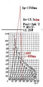
i intrest OTL just after saw your web
for 6C33
could u tell me what's wrong with the below fig
Attachments
could u tell me what's wrong with the below fig
Yes, many published curves on the 6C33C are not correct. With 0V on the grid the 6C33C can normally carry 2.5A at ~120V on the anode which means that you can get 25W in 8 ohm when using ~145V as anode voltage. In order to draw a loadline you should start at the idle conditions, normally 200mA works best so start with a point at 200mA and your chosen anode voltage then draw a line that has the same slope as the load impedance not the output impedance up to the point where it crosses the 0V grid voltage line.
Regards Hans
- Status
- This old topic is closed. If you want to reopen this topic, contact a moderator using the "Report Post" button.
- Home
- Amplifiers
- Tubes / Valves
- is it correct to calculate OTL?