Hello all,
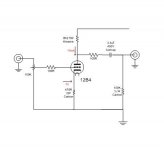
I have built the following 12B4 seen in the attached...only difference is i changed out the Cathode Resistor for three red LEDs. I remember getting between 7 and 9 volts across those LEDs for the bias. Sounds very nice.
Anyway, I would like to know if there's a simple way to calculate output impedance of a tube preamp - I read somewhere 1/gm, and maybe for a single tube pre setup as simple as the one attached, the 1/gm may be correct (gm of 12B4 is around .006 ohm??)
I also have a more complicated AN M7 Clone with two 5687 tube/channel and wonder how to calculate the output impedance for it too...(2/gm?)
I am concerned that with the low-ish input impedance of the Aleph5 or the Krell Clone I want to build, the two preamps may be too low for either of these to drive.
The UCD400 I have at 100K was no problem for either of these...
Attachments
Hello.
The calculation 1/gm is for cathode followers. For a Common Cathode amplifier as shown in your diagram the method is to treat the anode load and the valve's anode resistance as resistors in parallel i.e. R1 x R2/R1+R2
Using the one voltage you have given and looking at the GE curves on Frank's I estimate the anode resistance at your operating point to be about 1.4k. This gives a result i.e. output resistance of just over 1k plus of course your 100-ohm resistor.
Remember that anode resistance and gm are variables; the numbers given by the makers are when operating the valve close to bursting point so the numbers look good. Given gm for 12B4A is 6300 micromhos or 6.3mA/V.
I would say that you should run more current through your 12B4, at present you are a bit too close to the "knee" in the curves. This will increase gm and probably reduce noise. Another tip is to float the heatr at about +40V; 12B4s are notorious for poor heater/cathode insulation.
7N7
Edit: Sorry overlooked the 5687 bit. A paralleled pair of identical valves will have half the output resistance of a single valve.
1K +100R = 1.1kR on the my 12B4 Output Impedance. Cool. Should be OK with the Krell (22K Zin), but the Aleph may be a prob (11K Zin)
I see we add that last resistor - I see lot of Tube Pre designs with a 1Meg resistor to ground at output - doesn't this raise the output impedance of the pre to a value most amps can't work with?
Also, about the raising the current on the 12B4..,B+ is 220V and I think I am at 15ma. because I get around 90V at the plate.
More current would be lower the Plate Resistor (currently 8.2kR) or change the LED from red to blue or add another Red (raise voltage)?
Sorry, It has been a while since working on tube preamps...
EDIT:
Whoops, you added the 100R not the 100k to ground...I understand...
And if I remember correctly the cathode end determines the current, so changing the plate resistor won't change current...correct?
Changing the anode resistor will change the current as it will increase the voltage across the valve for a given value of cathode bias. However, best to keep the anode resistance high as this reduces distortion. Looking at the curves if I were you I would though reduce the value of the load resistor say to 6K or so. You will then be more on the characteristic
So reduce the bias and increase the current; you probably do not need to swing many volts to drive your power amplifiers so there should be no problem.
7N7
So reduce the bias and increase the current; you probably do not need to swing many volts to drive your power amplifiers so there should be no problem.
7N7
I see we add that last resistor - I see lot of Tube Pre designs with a 1Meg resistor to ground at output - doesn't this raise the output impedance of the pre to a value most amps can't work with?
If I understand what you are asking. The 1M resistor is usually at the output to keep the capacitor output from floating. If it weren't there and you were using the preamp into a source selector switch it would cause a pop in the speaker whenever you select it as a source. 1M is low enough in value to keep the cap output at ground potential. However it is still high enough in value to where you won't have to increase the size of the coupling cap to prevent low frequency roll off.
Your placement of the 100R and the 100K look fine as in your posted schematic. It will work.
You only need that 100R if you are worried about protecting it from a shorted output, or if it is there to attenuate the signal into a desired load. Otherwise it can be removed.
That 100k can be changed to 1M and the output coupling cap can be reduced to 1uF.
Of course these are just suggestions, I don't intend to cramp your style.
Calc is good, and all the above is good, but you're dealing with some variables that aren't carved in stone. After the calc, why not load the preamp with a resistor to the point where you have some small but easily measured drop in signal, and use ohms law. Imagine the amp is a perfect voltage source feeding a resistor (the output impedance). With no load, the voltage will be the same on both sides of the imaginary resistor. When you load it, the voltage drops on the output. You now have a simple voltage divider where you can calculate the upper resistor. Do it at 20Hz and 20kHz, or whatever limits you like.
When the load resistor pulls the signal down to half, that's also the output impedance, but IMO it throws everything in the circuit off, so I wouldn't go down that path. Just use a load that drops the signal 5% or so.
When the load resistor pulls the signal down to half, that's also the output impedance, but IMO it throws everything in the circuit off, so I wouldn't go down that path. Just use a load that drops the signal 5% or so.
hey-Hey!!!,
Conrad has the proper idea to measure it. Keep in mind that the couplng cap is in series, and at low frequency it will add substantially to the output Z. Still it would be best to measure in a few different output frequencies just to know what's in there. 20, 200 and 2k cps for instance.
cheers,
Douglas
So if I understand correctly, place a resistor across one channel output to ground and feed a signal (20 HZ, 1KHZ, 20KHZ) to preamp and, measure the voltage drop across the resistor and get current.
I have seen this method from Ron Elliott ESP site for amplifiers, and should work equally well with a pre, correct?
Can I use a 8 ohm resistor or should it be more like the impedance of an amp (50kR)
I have seen this method from Ron Elliott ESP site for amplifiers, and should work equally well with a pre, correct?
Can I use a 8 ohm resistor or should it be more like the impedance of an amp (50kR)
Can't say exactly what you need, but try about 1-2kohms. You need the voltage before you apply the resistor, then with the resistor. The voltage across the resistor will give you the current (V/R). The initial voltage minus the loaded voltage is the voltage across the imaginary resistor that represents the output impedance. Now you know the current through it, and the voltage across it, so the output impedance is just volts/current. It's late- I hope I got that right...
Output impedance
Hi all,
A very simple method to measure output impedance is as follows.
Feed a 1Khz sinewave in and adjust the output level to a sensible figure, say 1V.
Then place a 5K or so variable resistor across the output and adjust it such that the level has dropped to exactly half ie 500mV -6dB, remove the variable resistor and measure it, that is the output impedance of the unit. Obviously you can repeat this for various frequencies
John Caswell
Re: Output impedance
I would use 100K, 22K and 5k1 as loads and calculate the output impedance (from the measured output voltage) for each of these loads. The output impedance will vary slightly between each load value.
I recommend keeping the high value DC blocking cap on the output.
1uF and 10k or 22k input impedance curtails the bass too much.
For the Aleph, maybe even going as high as 8uF could be worth trying.
If you do adopt the DC blocking cap at the pre-amp output end then you can bypass the DC blocking cap at the power amp input end. If you don't bypass one of them then you will lose even more bass response.
That method puts in too severe a load.John Caswell said:A very simple method to measure output impedance is as follows.
Feed a 1Khz sinewave in and adjust the output level to a sensible figure, say 1V.
Then place a 5K or so variable resistor across the output and adjust it such that the level has dropped to exactly half ie 500mV -6dB, remove the variable resistor and measure it, that is the output impedance of the unit. Obviously you can repeat this for various frequencies
That is what Conrad was warning about.When the load resistor pulls the signal down to half, that's also the output impedance, but IMO it throws everything in the circuit off, so I wouldn't go down that path.
I would use 100K, 22K and 5k1 as loads and calculate the output impedance (from the measured output voltage) for each of these loads. The output impedance will vary slightly between each load value.
I recommend keeping the high value DC blocking cap on the output.
1uF and 10k or 22k input impedance curtails the bass too much.
For the Aleph, maybe even going as high as 8uF could be worth trying.
If you do adopt the DC blocking cap at the pre-amp output end then you can bypass the DC blocking cap at the power amp input end. If you don't bypass one of them then you will lose even more bass response.
The preamp has a 2.2uF 400V Auricap at the output. Wasn't planning on having a DC blocking cap on the amp input - hope this isn't stupid - if t is someone alert me soon- The other side of this 2.2uF cap is full plate voltage of around 90VDC - as shown above diagram.
The P-101 amp I built I purposely deleted the 2.2uF input electrolitic since I had it on the pre out...
If the existing 2.2uF seems too small, I have a 4.7uF, 10uF, 20uF and 28uF Polypropylene available...
The P-101 amp I built I purposely deleted the 2.2uF input electrolitic since I had it on the pre out...
If the existing 2.2uF seems too small, I have a 4.7uF, 10uF, 20uF and 28uF Polypropylene available...
I'd consider 2.2uF good for driving a total load of 46K or higher. General rule of thumb I use for coupling caps is:
1uF for coupling into 100K load
so that means 10uF will work for 10K, .1uF work for 1M, ect.
For values like 2.2uF sometimes it's easiest to drop the .2 and just say for 50K load.
Smaller cap value relation can still give an acceptable cutoff frequency, but phase shift in bass frequencies can become significant. I find using a cap any larger in value to be overkill, as it won't really improve anything, it will just take up more space and add cost. Using an oversized cap can also pass excessive, unwanted, subsonic frequencies.
%99 of the time your fine leaving the input cap out. I never use input caps.
7N7 said:Hello.
For a Common Cathode amplifier as shown in your diagram the method is to treat the anode load and the valve's anode resistance as resistors in parallel i.e. R1 x R2/R1+R2
I estimate the anode resistance at your operating point to be about 1.4k.
You have overlooked the cathode resistor, which is unbypassed.
The true output impedance becomes:
Rout = [(ra + (mu + 1)*Rk) * Ra] / [(ra + (mu + 1)*Rk) + Ra]
= [(1.4k + (8* .47k)*8.2k] / [(1.4k + (8*470)) + 8.2k]
= 3.1k
Plus your 100R resistor.
Merlinb,
did you derive
(mu+1) = (8*470)
From
mu = 7(mu of the tube) + 1 = 8
* 470 (cathode resistor)
Correct?
Why wouldn't it be:
((7*470)+1)
I'm not much of a mathematician, but the way that formula is written out seems miss-leading.
Seems like it should be:
((mu + 1)Rk) instead, based on the way you calculated.
Please elaborate. I know little about the math for unbypassed cathode resistors.
Merlinb said:
You have overlooked the cathode resistor, which is unbypassed.
The true output impedance becomes:
Rout = [(ra + (mu + 1)*Rk) * Ra] / [(ra + (mu + 1)*Rk) + Ra]
= [(1.4k + (8* .47k)*8.2k] / [(1.4k + (8*470)) + 8.2k]
= 3.1k
Plus your 100R resistor.
Quite right; it would never occur to me not to by-pass a cathode resistor, hence the error. 3.1k is a little on the high side for a line stage, depending upon the length of the cable and its capacitance of course.
Apologies to all concerned.
7N7
Jeb-D. said:Merlinb,
did you derive
(mu+1) = (8*470)
From
mu = 7(mu of the tube) + 1 = 8
* 470 (cathode resistor)
Correct?
Yes. Sorry, I didn't make the equation quite as clear as it coudl have been. (mu+1)*Rk
- Status
- This old topic is closed. If you want to reopen this topic, contact a moderator using the "Report Post" button.
- Home
- Amplifiers
- Tubes / Valves
- How to calculate Tube Preamp output impedance?