I ran across this and would like your comments. I would like to do something like this except to use a 6SN7 as the second tube and some of SY's 6BG6's as output tubes.
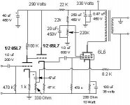
If there were roughly 150 volts on the grid of the 2nd half of the 6SL7 and 290 on the plate what would be across the 47K cathode resistor?
How could this amp be changed to provide the most power and best sound on a basement level price?
If there were roughly 150 volts on the grid of the 2nd half of the 6SL7 and 290 on the plate what would be across the 47K cathode resistor?
How could this amp be changed to provide the most power and best sound on a basement level price?
Attachments
7N7
Thanks for the reply
I can't find a circuit for the LM317 regulator so I could use it in a high voltage application. I did however find a circuit that uses a 1XCY 10M45S Would I be correct in assuming that this would work as good also? How about (2) VR150 tubes? How about a CCS like SY talked about before?
Given the 330 volt input to the divider I am assuming that it would output 300volts to G2. Current draw being about 1mA?
Could I just plug in a 6SN7 in place of the second 6SL7 tube?
There is a thorough description of building HV 317 regulators in Morgan Jones's Valve Amplifiers ; based on this I have built many successful regulators. You might find some data on the sites of some of the manufacturers such as Fairchild or National Semiconductor.
If you wanted to change over to 6SN7 then you would need to run more current through the valve - at present you are running about 3mA; it is said that 8mA is ideal for lowest distortion. Again see Jones.
There are many cleverer peple hereabouts especially with SE amplifiers which I have never built; I should wait a bit!!
Best of luck
7N7
Thank You 7N7
Found it I think I did page 239 Second edition of Valve Amplifiers by Morgan Jones.
There is a thorough description of building HV 317 regulators in Morgan Jones's Valve Amplifiers ; based on this I have built many successful regulators. You might find some data on the sites of some of the manufacturers such as Fairchild or National Semiconductor.
Found it I think I did page 239 Second edition of Valve Amplifiers by Morgan Jones.
burnedfingers said:Thank You 7N7
Found it I think I did page 239 Second edition of Valve Amplifiers by Morgan Jones.
The explanation is better in the third edition - especially useful for dummies like me!
7N7
The explanation is better in the third edition - especially useful for dummies like me!
It would appear that I am the only dummy here.
Don't have the third edition yet.
burnedfingers said:If there were roughly 150 volts on the grid of the 2nd half of the 6SL7 and 290 on the plate what would be across the 47K cathode resistor?
The tube will probably bias up at around 6 or 7 V, so the cathode voltage will be that much higher than the grid: roughly 155V or so.
Picking a cathode resistor is easy: decide how much current you want through the tube and use Ohm's Law. If you want 8mA then 155V/8mA=19k ohms. Or working from the other direction, 155V/22k=7mA.
If you do build the amp, you might try it with and without the cathode follower. The 6SL7 might have no trouble driving the output tube directly from the plate and it might end up sounding better. It's just something you'll have to try.
As for regulating the screen supply, the way that *I* would do it is to first build the amp without regulation and listen to it for a while. If I'm still interested in the project, then I might try regulating the screen supply, perhaps trying more than one method (shunt reg tubes are even easier than 3 pin SS regulators.) I'm more likely to get something up and running if I keep it simple, and in the end I learn more by making changes incrementally.
-- Dave
Not knowing what the actual cathode voltage was kinda threw me. So I am probably looking at 3.30 mA on the second half of the 6SL7.
I would like to keep the 6SL7 input stage and change the 2nd stage to a 6SN7. I realize the single tube would probably have enough grunt because I have a Wurlitzer amplifier that uses 1 6sN7 to drive a 6L6 PP output stage. Anyway I just like the 6SL7/6SN7 line up.
I will try the tube regulators and then triode operation and see how it sounds.
This will probably end up to be something that I will try different output tubes in. Is there an adapter that will plug into a 8 pin octal socket and allow me to use a 807 tube?
I hope you will forgive this but I am going to try out a pair of 125ESE Hammond transformers that have been sitting on my shelf for years.
- Status
- This old topic is closed. If you want to reopen this topic, contact a moderator using the "Report Post" button.
- Home
- Amplifiers
- Tubes / Valves
- re design of a SE tube amplifier