Newbie question,
Concerning the JB Aikido PCB for a linestage: 12au7, 250V
I am using a seperate transformer for 12.6 heater supply. With the 1/4B+ bias, should the caps in the HS be rated for the 12.6V (30V caps) or 12.6 + 65V (100V minimum)?
I realize the HS is ~12.6 as relative to itself, and not chassis GND (earth) but does the Cap value pertain to the overall Voltage?
I've read that a MOV across the + and GND at the Power switch will help prevent turn on/off thump? Any experience with this?
One more Q if you please....
Is the B+bias to heater wire tied directly to the (-) of the heater on the PCB? or am I totally lost????
Learning is Fun!!
Ron
Well, after 70 views on this subject with no replys.....
Either;
I asked a question too stupid to be worthy of an answer ....
or....
There are many others who wonder about the questions and need an answer too.
So. I read a sheep load and found my own answers!!!
1)Voltage ratings of the capacitors in the heater supply are relative to themselves.
ie: 12.6V heaters with a B+ bias of 70volts will be fine with a 25V capcacitor.
2) MOV across the + and ground at the turn on switch WILL help prevent turn on thump.
3)The B+ bias to the heater PS goes to the Center Tap of the heater windings. Giving them the (neutral) reference point from where to start the 12.6V for the heaters.
Baby steps, I know....but we all started at the same point.
(Except Sy, he was born knowing this stuff)")
Ron
Either;
I asked a question too stupid to be worthy of an answer ....
or....
There are many others who wonder about the questions and need an answer too.
So. I read a sheep load and found my own answers!!!
1)Voltage ratings of the capacitors in the heater supply are relative to themselves.
ie: 12.6V heaters with a B+ bias of 70volts will be fine with a 25V capcacitor.
2) MOV across the + and ground at the turn on switch WILL help prevent turn on thump.
3)The B+ bias to the heater PS goes to the Center Tap of the heater windings. Giving them the (neutral) reference point from where to start the 12.6V for the heaters.
Baby steps, I know....but we all started at the same point.
(Except Sy, he was born knowing this stuff)
Ron
You need the 100V capacitor for the filament supply bias cap - the important point is that the bias supply impresses 70Vdc across the capacitor. The 12.6V floats on top of the 70V, but can be ignored because all of the heater current actually flows through a loop that does not include the capacitor.
You can use 25V electrolytics in the filament supply. Just make sure that the cases are floating and reasonably well insulated from the chassis so that your 70V bias is not shorted.
Turn on thump can be avoided with a relay and a timer ic, shorting the output to ground until the tubes warm up. Alternately a simple switch can do the same thing if you remember to use it. Use a tube power amplifier and this issue goes away.
A mov won't prevent the output transient that occurs during warm up because it happens many seconds after the power is applied in a tube pre-amplifier.
Renron,
There's a neat circuit for preventing turn-on thump. It uses a timer relay (vacuum tubed works) and a cheap Omron relay (can be purchased at Radioshack).
The delay is wired so that the timer is wired via the closed contacts of the Omron relay. When powered-up, the timer times (say 10 seconds) then trips the Omron, which switches on the B+ transformer and simultaneously switches off the tube timer relay. The reason is that this allows a pretty instanteous reset in case of a power failure AND it means that the more expensive tube timer has nothing across it when the amp is actually being used. OH YES, I forgot to add that while the timer is doing its timing thing, the heaters are warming-up quite nicely!
I can post the circuit if you want it. NOS Amperite relays are fairly cheap on Ebay.
Charlie
Renron, actually it doesn't really reduce turn-on thump, as that is caused by your B+ rectifier, but it does allow your tues to pre-heat.
In the end, I opted for tube rectification for B+. It takes around 10 seconds to come up to full power (using a 5V4). Plus, I also really like the looks of a large power rectifier on my Aikido - it has a pretty orange glow from the filaments. But the Amperite / Omron combination worked perfectly when I had it installed in my Aikido. As for turn-on thump, I expect that with tube rectification I get no turn-on thump, but I haven't tried to find out. I purchased a Belkin PureAV console which "filter" my power, but also has a timer for banks of items. I simply have my main amp set on the Belkin with a 15 second delay - I hit one switch and the Aikido, CD-player, phono-preamp, whatever all switch-on, then after 15 seconds, my main amp switches on.
Charlie
kevinkr said:You need the 100V capacitor for the filament supply bias cap - the important point is that the bias supply impresses 70Vdc across the capacitor. The 12.6V floats on top of the 70V, but can be ignored because all of the heater current actually flows through a loop that does not include the capacitor.
Seems counter intuitive that all of the heater current flows thorugh a loop that does not include the capacitors.? Doesn't the current flow through all of the components in a circuit?
Hey, I'm a newb.
You can use 25V electrolytics in the filament supply. Just make sure that the cases are floating and reasonably well insulated from the chassis so that your 70V bias is not shorted.
If the heater CT is connected to the B+bias (~70V) is the heater PS not then floated? And the heater PS circuit referenced to itself? (12.6V) Would it be different without a CT? using a bridge? I understand about differing ground voltages, and the difference between circuit ground and chassis earth ground.
Turn on thump can be avoided with a relay and a timer ic, shorting the output to ground until the tubes warm up. Alternately a simple switch can do the same thing if you remember to use it. Use a tube power amplifier and this issue goes away.
A mute(ing) switch seems like a good idea anyway, thanks
A mov won't prevent the output transient that occurs during warm up because it happens many seconds after the power is applied in a tube pre-amplifier.
Ah, I understand, I got the MOV idea from a SS amp forum.
Seems counter intuitive that all of the heater current flows thorugh a loop that does not include the capacitors.? Doesn't the current flow through all of the components in a circuit? If the heater CT is connected to the B+bias (~70V) is the heater PS not then floated? And the heater PS circuit referenced to itself? (12.6V) Would it be different without a CT? using a bridge? I understand about differing ground voltages, and the difference between circuit ground and chassis earth ground. A mute(ing) switch seems like a good idea anyway, thanks Ah, I understand, I got the MOV idea from a SS amp forum. Charlie,
I read in a different post where Sy, the tube god, helped you to achive a silent Aikido preamp. Well done, and thanks for sharing your insights with us.
I remember Sy posting a while back saying that he does not delay B+, but turns on both heaters and B+ at the same time. As long as there is no input signal until the valves warm up, there should be no problem. I don't have a link to that post, sorry.
Sy, If I am wrong about what I thought you said please correct me.
Thanks for all the posts on your Aikido Charlie....you may be getting a few PM from me asking for help.
Thanks,
Ron
If I might clarify, the capacitors filtering DC for your heaters only need to be rated for the 12.6V and ripple (besides, 100V 10,000uF caps are expensive). It is the B+ divider that is providing the reference voltage, and uses a cap to stabilise that voltage, that needs the high rating.
JNB,
Sorry to ask, but could you please explain the "uses a cap to stabilise that voltage, that needs the high rating."
Are you using caps for the voltage divider? I saw as schematic where this was done.
Or, are you refering to using a cap at the end of the B+ voltage divider circuit where it terminates to gnd?
I hope that came out clear.
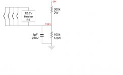
B+ -------|---------
|
R
|
|
|-----------B+bias tap to CT of heater
R
|
|
cap |-------------C-------GND very small value high voltage
|
GND
Like this?
Ron
Sorry to ask, but could you please explain the "uses a cap to stabilise that voltage, that needs the high rating."
Are you using caps for the voltage divider? I saw as schematic where this was done.
Or, are you refering to using a cap at the end of the B+ voltage divider circuit where it terminates to gnd?
I hope that came out clear.
B+ -------|---------
|
R
|
|
|-----------B+bias tap to CT of heater
R
|
|
cap |-------------C-------GND very small value high voltage
|
GND
Like this?
Ron
That is the simplest of several ways to do it and I assumed you had done it that way. I sometimes do it that way myself.
BTW, the cap goes from earth to the tap, in parallel with the lower resistor. This is the higher voltage one.
Your lower voltage smoothing cap (ie, the heater supply) only connects to the B+ supply tap at one point, and doesn't connect directly to earth. This is why there isn't high voltage across it.
JNB.
Thank you for the very clear explaination of the smoothing cap.
I tried to "draw" it out that way with the cap being in || with the last resistor but after editing my post twice, it just would not come out the way I wanted it to look.
Your help and time ARE much appreciated, as are everyone else's time too.
Charlie, you know this better than I, how much we appreciate the helping hand of those with experience.
Ron
- Status
- This old topic is closed. If you want to reopen this topic, contact a moderator using the "Report Post" button.
- Home
- Amplifiers
- Tubes / Valves
- Newb Questions RE: HS caps & B+ Bias