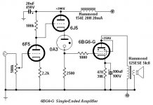
This is my next in line to be built I think. I have a few beautful ST shaped 6BG6-G's to use up, although you could substitute any 6L6 variant.
Q: if I added a 2nd output tube and changed the whole thing to parallel feed, does the DC current rating of the output transformer matter at all anymore? Or do you still need to obey the ratings? And... do you choose the same primary impedence as though you were using the tranfrmr in the standard manner? So, in this case, 2500 ohms? (2x 6L6)
Q: if I added a 2nd output tube and changed the whole thing to parallel feed, does the DC current rating of the output transformer matter at all anymore? Or do you still need to obey the ratings? And... do you choose the same primary impedence as though you were using the tranfrmr in the standard manner? So, in this case, 2500 ohms? (2x 6L6)
Attachments
Hi Joel,
My answers to your questions are:
1) Parallel feed has a capacitor at one end of the transformer so no dc can flow through the OPT.
However I find a small gap i.e. 10mA worth of dc current gap helps OPT performance so I always spec. my PP transformers for 10mA dc current...
2) The value of OPT impedance should indeed be as per two parallel tubes so 2500 is fine.
I would go for slightly higher impedance and sacrifice a little power for more linear performance...
Hope this helps
ciao
James
...Sorry...
Joel,
Sorry, I completely misunderstood your question I thought it was strange that you didn't realise the answer
To answer your question... to a first approximation, you would rate the OPT as you would a PP transformer with the two valves ...so in CLASS A1 triode connected about 4-5 watts and Class A pp ultralinear about 15 watts
hope thats a better answer...
James
Joel,
Sorry, I completely misunderstood your question
I thought it was strange that you didn't realise the answer To answer your question... to a first approximation, you would rate the OPT as you would a PP transformer with the two valves ...so in CLASS A1 triode connected about 4-5 watts and Class A pp ultralinear about 15 watts
hope thats a better answer...
James
Assuming the same transformer is used, (125ESE), the AC voltage across it will be exactly the same. AC current will double, but you weren't going to listen to sine waves, were you? You'll use a different secondary tap, of course. The low frequency saturation will occur at the same point (twice the power, though, with two tubes), the low level bass response will extend a litle lower, and the high frequency end may suffer a little compared to a single tube. Maybe your dog can hear the difference
My first thought is with no DC in the core using up magnetic headroom you would be able to push the tranny harder with AC signal.
You could either push more power through the tranny or go lower in frequency before saturation would raise it's ugly head.
Gary, (who has never built a non parafeed SE amp...)
You could either push more power through the tranny or go lower in frequency before saturation would raise it's ugly head.
Gary, (who has never built a non parafeed SE amp...)
Gary P said:My first thought is with no DC in the core using up magnetic headroom you would be able to push the tranny harder with AC signal.
You could either push more power through the tranny or go lower in frequency before saturation would raise it's ugly head.
Ah ha! That's exactly what I was getting at, Gary. Let's take the 125ESE for example: it's rated at 80mA DC, and the frequency response at 15W is 150-15kHz +-1dB... not so hot. But I and others have observed that with 30mA or so of plate current, and low Rp in the output tube, you can easily get it flat from 20-20kHz. So... eliminating the DC altogether should show further improvement.
EXTENDING THE BANDWIDTH.
Hi Joel,
Isn't that rather obvious?
I wouldn't expect miracles though, but parafeding should help here if you're happy having the cap there.
Cheers,
Hi Joel,
But I and others have observed that with 30mA or so of plate current, and low Rp in the output tube, you can easily get it flat from 20-20kHz. So... eliminating the DC altogether should show further improvement.
Isn't that rather obvious?
I wouldn't expect miracles though, but parafeding should help here if you're happy having the cap there.
Cheers,
Frank says
[but parafeding should help here if you're happy having the cap there.]
Keep in mind that if you are doing a standard series feed output arrangement you also have that cap in the singal path. It's the last cap in the power supply.
Parafeed does not add an additional cap to the signal path. It mearly moves one that is already there.
Gary

Nah, the power supply still has a capacitor.
I was looking at things from the AC current analysis point of view.
In a series feed SE amp the final cap in the power supply has 2 jobs. It is the final noise filter element for the power supply and is the primary signal return path to ground. From there it goes up the cathode bypass cap to the cathode of the triode closing the loop.
In a parafeed arrangement the final cap in the power supplys job is to be the final filter element for power supply noise. The parafeed cap is now the primary signal return path to ground. The parafeed choke (or CCS) helps to isolate the signal path from the power supply. The signal path is closed by the cathode bypass cap returning the current to the cathode of the triode.
Yes, there is a extra cap in the parafeed design. As for the number of caps in the AC signal path that remains the same.
Another trick that can be done with parafeed is to return the the transformer primary directly to the cathode of the output triode. In this form we have now removed 1 cap from the output stage signal loop. The loop now consists of the triode, parafeed cap, and transformer primary. In both examples above the signal loop is the triode, transformer primary, parafeed/final cap in power supply, and the cathode bypass cap.
Ultrapath does a similar trick with the cathode bypass cap returning to B+ instead of ground. This also shortens the AC signal loop. But Ultrapath doesn't provide the extra isolation of the parafeed choke (or CCS) though, and the output transformer has to handle the DC bias current.
Here is an example of how small the output signal loop can be. Put your coice of parafeed choke or CCS on top of the 45 to complete the picture...
<img src=http://home.pacifier.com/~gpimm/45_out.gif>
PARACOMMANDO.
Hi,
Now that is a neat trick I find rather appealing.
Sidebar:I find the way you analyse a circuit according to it's current very attractive too.
It would be a great help to most people if more circuit diagrams would be presented that way.
Thanks Gary,
Hi,
Another trick that can be done with parafeed is to return the the transformer primary directly to the cathode of the output triode.
Now that is a neat trick I find rather appealing.
Sidebar:I find the way you analyse a circuit according to it's current very attractive too.
It would be a great help to most people if more circuit diagrams would be presented that way.
Thanks Gary,
- Status
- This old topic is closed. If you want to reopen this topic, contact a moderator using the "Report Post" button.
- Home
- Amplifiers
- Tubes / Valves
- Gas-coupled 6L6/6BG6-G SE