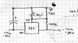
I wanted to try an LTP with CCS, so I have converted an amp from Paraphase phase splitter to LTP with cathode CCS.
The circuit diagram is here
I am a little puzzled by what appears to be intermodulation with the 100Hz mains ripple.
The level might not be critical as it is more than -60dB down, but I am a little curious as to its cause since it was not noticeable with the old-fashioned paraphase input stage. Spectrum plot with Paraphase is here
I have tried to significantly increase the capacitance of the negative supply. This only reduced the IM peaks by about 3dB. Improved filtering of the B+ did not seem to have any effect.
Is my CCS not good enough, or should I just stop worrying and play some music?
Sven.
Svein_B said:I wanted to try an LTP with CCS, so I have converted an amp from Paraphase phase splitter to LTP with cathode CCS.
The circuit diagram is here
I am a little puzzled by what appears to be intermodulation with the 100Hz mains ripple.
The level might not be critical as it is more than -60dB down, but I am a little curious as to its cause since it was not noticeable with the old-fashioned paraphase input stage. Spectrum plot with Paraphase is here
I have tried to significantly increase the capacitance of the negative supply. This only reduced the IM peaks by about 3dB. Improved filtering of the B+ did not seem to have any effect.
Is my CCS not good enough, or should I just stop worrying and play some music?
Sven.
I think that the CCS may be benefited by an LM337T stabilized -V supply. In my first experiments (Schmitt & CCS thread) with an alike CCS (no sonic evaluation yet bcs I decided to rebuild the amp's innards so it can be handier), I had suspicions of some 100Hz trembling in the drawn current. Maybe we can make a voltage doubler off the filament voltage and then have spare to stabilize. What is your early sonic evaluation VS a resistor tail? Many are pro tail CCS and some say it sounds non relaxed.
The amp used for these tests does not have any hum problems as such, I measure less than 1mV on the speaker terminals.
According to Morgan Jones (from Google Books bottom of page 134):
As shown, the cascade current source is relatively sensitive to hum and noise on the negative supply because of current changes through the voltage reference. This sensitivity can be greatly reduced by modifying the circuit to include a current regulator diode in the chain that feed the voltage reference. See Fig. 2.48c
I have however no idea of how ripple from the CCS may affect the LTP behaviour.
SveinB.
Also, if you have the capability to measure differentially, it may be worthwhile to see what's happening at the LTP plates. They need to be loaded symmetrically, so a single-ended measurement can be misleading.
Since you have a 250V rail available, you might make the feed resistors to the LED reference bigger (say, 47k) and return them to that supply rather than ground. That will give a more constant current to the reference.
Since you have a 250V rail available, you might make the feed resistors to the LED reference bigger (say, 47k) and return them to that supply rather than ground. That will give a more constant current to the reference.
Yvesm said:
Your shots are not at the same scale, looking closely there is just 2dB difference.
Did you test without the gNFB loop which could hide real behaviour ?
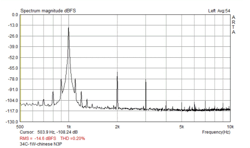
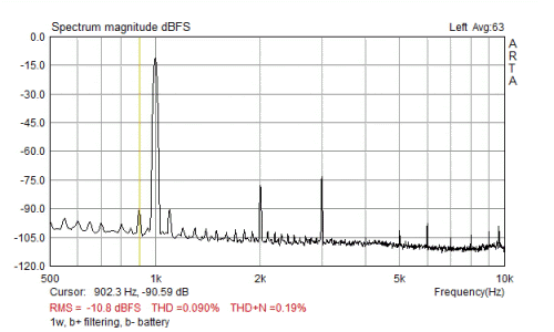
Unfortunately the graphs are not the same scale, but both are done at 1W. The difference in level from the 1KHz to the IM "sidelobbes" are:
- Paraphase: -76dB
- LTP with CCS: -63 dB
- Another test done , LTP without gNFB (second grid grounded): -52 dB
SY said:Also, if you have the capability to measure differentially, it may be worthwhile to see what's happening at the LTP plates. They need to be loaded symmetrically, so a single-ended measurement can be misleading.
Since you have a 250V rail available, you might make the feed resistors to the LED reference bigger (say, 47k) and return them to that supply rather than ground. That will give a more constant current to the reference.
I do not presently have the possibility to measure spectrum directly at the plates. I did however make measurements by disconnecting alternate coupling caps to the output stage. The results without gNFB showed -52dB IM from both input halves of the LTP triode (as well as some more hum, and a richer overtone spectrum).
It would appear that the remaining issue to investigate is the CCS. It is known that the cascaded BJT CCS is somewhat sensitive to ripple. I do however still not know how this is assumed to affects the LTP performance .
Using a larger cap for the negative supply reduced the B- ripple from 35mV p-p to around 10mV p-p. This reduced the IM distortion by about 3dB.
I do assume that using some form of MOSFET for the CCS instead of the LED based CCS may give better performance (or feed the LED from B+ as suggested).
Looking at some other measurements it does seem that -63dB is by no means terribly bad compared to other amplifiers, but many (especially those with paraphase and concertina) have considerably less of this type of IM distortion.
Unfortunately the graphs published by Stereophile use a linear scale that mostly hide this "artifact". I do however suspect that the thickening of the bottom part of the 1Khz peak represent the ripple-induced IM. Here are a couple of examples: manley Stingray (-60 at 33w), and Eico HF-81 (-80dB at 1W - Concertina!).
Svein.
Yes, the LED is a source of some RF noise, but from my observatiosns very high in frequency and I think not liekly to cause any trouble for the matter discussed.Gordy said:Just a thought... CCS represents a high impedance node and may possibly pick up RF generated by solid state diodes.
SveinB.
I have done some Sunday measurements and soldering.
Summary of my observations
The differential LTP produces intermodulation distortion (IMD) from power supply ripple, both from ripple on the negative “tail” and from the anode supply. The intermodulation produced by the differential LTP seems to be considerably larger than from a grounded cathode / paraphase under similar conditions
Recap
I started with a paraphase input stage. At 1 watt it produced 0.2% THD and IMD products from 100Hz PS ripple at approximately -76dB. When replacing the paraphrase with an LTP with cathode CCS, the IMD increased to -63dB.
Improving the negative supply / CCS
The suspected source of this increase in IMD was the CCS and the corresponding negative supply. Feeding the CCS LED from the B+ was suggested in order to reduce this ripple. Surprisingly this only reduced the IMD by 2-3 dB. Replacing the whole negative supply with a 9V battery gave no further improvement. Preliminary hypothesis was therefore that the IMD was not caused by the negative supply (to be reversed a little further down).
Improving the anode supply
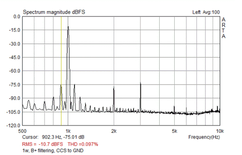
The only ripple now present to the LTP was the anode supply. Additional RC filtering was installed for the LTP stage which reduced the ripple from around 35mV p-p to just a few mV.
This provided a considerable improvement!. IMD is now way down at -80 dB")
(the scan is now with a different smoothing window compared to the earlier ones for improved clarity)
Since the cathode supply was found to not be the source of the IMD, it should now be safe to remove the 9V battery and wire the CCS as before, with LED fed from GND.
Wrong! The IMD is now up again to -64 dB
It is now clear that it is necessary to have both a clean anode supply, and cathode supply to get low IMD. Feeding the CCS LED from the 250V positive supply by a 68K resistor may now help to get things right.
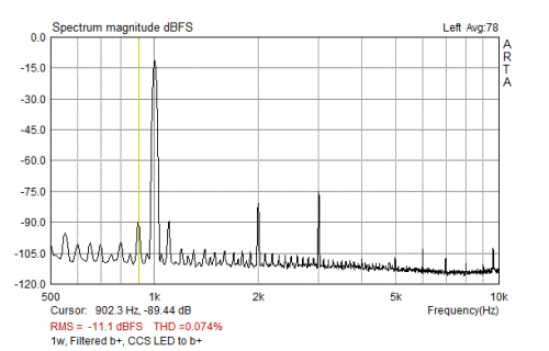
Yes! IMD is -78dB, this is almost as good as with a battery for the negative supply, and about par with the original paraphase (but with much better power filtering). I am satisfied and can turn the amp right way up for listening (until the next rebuild).
Closing remarks
Little information has been found on the subject of power-ripple IMD. I am not sure how detrimental it is to the sound, but I just do not feel that it should be accepted if it could be avoided. I have also learned that a LED/transistor CCS need special care to get clean current, and will in the future also be looking for some 2-point CCS solutions based on JFET, IXYS, or DN2540 (if I can find the parts).
What do you think. Am I on the right track, or chasing ghosts?
SveinB
Summary of my observations
The differential LTP produces intermodulation distortion (IMD) from power supply ripple, both from ripple on the negative “tail” and from the anode supply. The intermodulation produced by the differential LTP seems to be considerably larger than from a grounded cathode / paraphase under similar conditions
Recap
I started with a paraphase input stage. At 1 watt it produced 0.2% THD and IMD products from 100Hz PS ripple at approximately -76dB. When replacing the paraphrase with an LTP with cathode CCS, the IMD increased to -63dB.
Improving the negative supply / CCS
The suspected source of this increase in IMD was the CCS and the corresponding negative supply. Feeding the CCS LED from the B+ was suggested in order to reduce this ripple. Surprisingly this only reduced the IMD by 2-3 dB. Replacing the whole negative supply with a 9V battery gave no further improvement. Preliminary hypothesis was therefore that the IMD was not caused by the negative supply (to be reversed a little further down).
Improving the anode supply
The only ripple now present to the LTP was the anode supply. Additional RC filtering was installed for the LTP stage which reduced the ripple from around 35mV p-p to just a few mV.
This provided a considerable improvement!. IMD is now way down at -80 dB
(the scan is now with a different smoothing window compared to the earlier ones for improved clarity)
Since the cathode supply was found to not be the source of the IMD, it should now be safe to remove the 9V battery and wire the CCS as before, with LED fed from GND.
Wrong! The IMD is now up again to -64 dB
It is now clear that it is necessary to have both a clean anode supply, and cathode supply to get low IMD. Feeding the CCS LED from the 250V positive supply by a 68K resistor may now help to get things right.
Yes! IMD is -78dB, this is almost as good as with a battery for the negative supply, and about par with the original paraphase (but with much better power filtering). I am satisfied and can turn the amp right way up for listening (until the next rebuild).
Closing remarks
Little information has been found on the subject of power-ripple IMD. I am not sure how detrimental it is to the sound, but I just do not feel that it should be accepted if it could be avoided. I have also learned that a LED/transistor CCS need special care to get clean current, and will in the future also be looking for some 2-point CCS solutions based on JFET, IXYS, or DN2540 (if I can find the parts).
What do you think. Am I on the right track, or chasing ghosts?
SveinB
No you are not chasing ghosts, low PSU modulation makes a better resolving amp always. Since I am rebuilding mine with almost the same CCS as yours, I will benefit from my fix bias - supply and feed the tail from -30V regulated. Have you had any good listen yet? What is your opinion regarding your amp before VS with tail CCS well shorted?
Attachments
Please remember that this is a balanced circuit and should be measured that way. What happens to these common-mode artifacts when the circuit is run into a balanced load? What's the impact on distortion and PSR when the diff pair is loaded asymmetrically (which you've done with your test)?
So, you may not be chasing ghosts, we may wish to pay some better attention to those supplies, but the situation might be better than your measurement indicates.
So, you may not be chasing ghosts, we may wish to pay some better attention to those supplies, but the situation might be better than your measurement indicates.
SY said:Please remember that this is a balanced circuit and should be measured that way.
. . .
The measurements are done with the complete amp, from input to speaker terminals. The diff pair should thus be loaded correctly, and the OPT representing the balanced load.
(there are many different trials described in my posts, so I may not have been clear enough in description of the different test environments).
SveinB.
I think you are going in the right direction.
I remember seeing CCS that have the 1k resistor replaced by combination of FET + resistor (that forms a mini CCS) to pin the current through the reference chain for the BC547 CCS.
Also, consider the DC current loop for the tail... from anodes to the the cathodes of the 5670, through the BC547s, through the 150 R reference resistor... and then fighting it's way back through the supply... it has to form a loop... so it may help if you can trace the physical path and make it as short and direct as possible.
Also, do you still have just the 100 + 200 microfarad caps in the -8V supply? If so it may be very worthwhile increasing them (or making it CRCRC), and retesting. (After all, your issue is about 100hz, and the twin diode rectifier is giving you about that).
Good luck.
Svein, got it, sorry for misunderstanding. And not surprisingly, taking the reference string toward a constant current itself made a big difference. You could put a CCS there, too...
FWIW, I'm using DN2540 cascodes as CCS and am VERY happy with how they perform. The do a great job of removing power supply criticality.
FWIW, I'm using DN2540 cascodes as CCS and am VERY happy with how they perform. The do a great job of removing power supply criticality.
- Status
- This old topic is closed. If you want to reopen this topic, contact a moderator using the "Report Post" button.
- Home
- Amplifiers
- Tubes / Valves
- LTP with CCS - IM Distortion