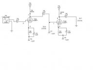
iam only simulation the tube preamp the total harmic distortion looks low i use circuit maker simulator the student version does not let you do any analyist on distortion
if their are any ways clear up distortion my guess way the schematic is now 5 to 10% dist
get a louder singal other then 1.5vpk
is the schematic in correct way or style
iam use this schematic for a guitar preamp dont scared off if dont know anything about guitar amp some times the only part got change in the preamp is capacitor that in the very first part of the preamp for me its 68k so if the amp was clip real bad while have a guitar in it i would change to 0.022uf that only part real need to change i have not built this amp or tryed it out if need or built in fuzz or overdrive
or distrortion be a different story
what wana try to achive with this preamp is nice clear guitar clean channel
also my power only limted to 12 vcc and if need be -- 12 vss
the schematic say 12au7 but iam will to try 12u7 only becase of the voltage limts
see any errors in preamp?????
also can get the audio out form 1.5v to 2.5v
clear up any distortion ????
Attachments
prorms said:see any errors in preamp?????
also can get the audio out form 1.5v to 2.5v
clear up any distortion ????
No, not really.
I have a couple of ideas. Add gNFB to help decrease distortion, and add a CCS to the output VT to perhaps get a bigger Vo. Given the very limited Vpp, you might want to CCS both stages. That'll not only get bigger swings, but will help linearize the VTs as well.
Attachments
First of all, I would not trust any simulation of the 12AU7 running at such low voltages. You'll just have to build the thing and see what happens. Play around with the biasing ....
If you have -12V available, then you have 24V total to use. See attached drawing. Notice that I've left out the bypass caps on the cathode resistors. That'll lower the gain, but give you more headroom. I don't know how much gain you need exactly, but two 12AU7's in series might give you enough even without the bypass caps.
I suspect that the real problem is the second stage. If it's not biased just right then it will clip too early. Leaving out the bypass caps will help a little, but you'll really need to play around with the bias to get it just right, and that means you'll just have to build the thing. You might try grid leak bias on the first stage (2M or bigger grid resistor, no cathode resistor) and cathode bias on the second stage (1M grid resistor, whatever cathode resistor works.)
Attachments
Check this out-
Not long ago I designed up a low voltage pre-amp that used tubes like the 6SN7, 5687 and the Nuvistor types, 7586, and its russian analog,6C51H-B.
I both simulated it and built it real-world, trimming and modifying to get a pretty good sounding set-up. It doesnt have g-NFB, but does have a fair amount of Local feedback....
It consists of a gain stage, and a cathode-follower stage, and is pretty simple to construct for testing.
Here is the thread- http://www.diyaudio.com/forums/showthread.php?s=&threadid=89195&perpage=25&highlight=&pagenumber=2
Its a few pages long, and two circuits are discussed, the commercial 'Tubaliser' -which gave problems- and the scheme I posted, which gives good results....
i changed the voltage form 12v and -12v
will tube still work correctly with voltages at 12+ and 12- will destroy the tube????
when changed the voltage the distortion clearup on the simulated fourier analyies
when i Add gNFB in the simulator look like might add some unwanted hum to the output singal??????
will tube still work correctly with voltages at 12+ and 12- will destroy the tube????
when changed the voltage the distortion clearup on the simulated fourier analyies
when i Add gNFB in the simulator look like might add some unwanted hum to the output singal??????
Attachments
pin 4 to the +12V rail, and pin 5 to ground (not the - supply) since on most SMPS's for instance, the +12V rail is rated at much higher current than the -12V rail. still need a grid resistor on the first grid between 1 and 5 megs returned to the -12V rail. don't evpect huge stage gains at 12V, or even 24V. in my guitar preamp i modeled it first, which only got me in the ballpark. after that i had to build it to get the final working version. it was a whole lot easier to attach a signal source and scope, and use a pot in place of a bias or current setting resistor, and adjust the pot for best gain, than it was to run sim after sim while changing that resistor in the simulated circuit. it gives you an opportunity to actually see what the effect of changing parts values actually does, instantly. sure , sim it to get "in the ballpark", but build and adjust to get it working the way you want it to.
btw i suggest changing those 1uf lytics out for 0.1uf monolithics/ mylars/ polys/ etc..... the lytics can mess with your grid bias if you're not careful, because they conduct in one direction like a diode
btw i suggest changing those 1uf lytics out for 0.1uf monolithics/ mylars/ polys/ etc..... the lytics can mess with your grid bias if you're not careful, because they conduct in one direction like a diode

- Status
- This old topic is closed. If you want to reopen this topic, contact a moderator using the "Report Post" button.
- Home
- Amplifiers
- Tubes / Valves
- is this ok to build???