Grid Resistors - Why Are They Used?
MI focused article, but sums it up pretty well. In HiFi they may be much lower, sometimes <300 ohms.
MI focused article, but sums it up pretty well. In HiFi they may be much lower, sometimes <300 ohms.
And further explanation here:
http://www.freewebs.com/valvewizard/gridstopper.html
http://www.freewebs.com/valvewizard/gridstopper.html
One thing that the article doesn't mention is that these stopper resistors are a good idea at the screens of both small signal pentode voltage amps, and pentode output stages. Since these conduct screen current, they should not be so large that they ruin the screen voltage regulation. Usually 1K5 or less will get the job done and damp out any RF oscillations or ringing. Even if you don't see any ringing, it's still a good idea to include a small screen stopper as a preventative measure. Usually 330R -- 470R is a good value here.
Here's where an o'scope is a most handy piece of equipment to have on hand.
Here's where an o'scope is a most handy piece of equipment to have on hand.
There is a bit more to grid stoppers which often gets missed. Many texts specify values between 1K-10K on output tube (g1) grids. Miller effect has been discussed to parasitic tube element capacitances and in some tubes i.e triodes isn’t insignifigant. The point I’m making is if one is designing an amplifier with global nfb, the total amp HF response/phase will be modified if the output stage grid (g1) stoppers are arbitarily changed. Physics models says it will.
For the moment I'm not covering o/p stage screen grid stuff....slightly different purpose.
For example my 4 stage p-p UL amp uses a ECF80 pent as a triode on input, into standard concertina p/s feeding 12BY7 wideband current sourced power drivers. The response without output tubes is fantastically wide to over 300Khz. The low impedance current source of the driver stage is an ideal match for dumping o/p stage Miller effect but only if low values of grid stopper are used, i.e 2K2 for 6550. The result is obvious, an improved stage HF response.
But there is the problem of the output transformer parasitics that the usable throughput frequency will be quite a lot lower. A top notch E&I output tranny will slip –3dB around 50Khz. Most fall way shorter than this. So our amp must have the HF response modfified. The output stage tube and drivers work fast, and to avoid ringing and phase problems, the 1st stage R/C component phase compensation will need changing to droop the HF response. With global nfb connected a 1Khz square wave examined on the 1st stage will look skewed.
For experiment, I changed the grid stoppers on my p-p 6550 output stage from 10K to 2K2 (effectively advancing the phase) and to maintain the correct phase response, the „R in series with the „C“ on the 1st stage had to be halved in value from 3K3 to1K3.
So anyone doing a Spice model should notice any changes made to the output stage components with global 20dB nfb should reflect changed values back at the input.
To wind this up, the front end tube in all p-p amps with global nfb has to be b/w frequency slewed to maintain stability, so there’s no point choosing a fast tube.
I wonder what effect to the sound quality different value grid stoppers have. I say reduced value grid stoppers improves sound definition. Who’s tried it and agrees ?
richj
Attachments
I agree with you on the large grid stop resistors will alter the phase linearity severe enough to alter the quality of the music reproduction...
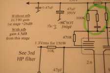
As for the schematic in the photo... I do not agree tha the Gain in a particular stage is reduced from global feedback , the Gain is unchanged, instead the input sensitivity has been reduced by the feedback factor...
Chris
As for the schematic in the photo... I do not agree tha the Gain in a particular stage is reduced from global feedback , the Gain is unchanged, instead the input sensitivity has been reduced by the feedback factor...
Chris
cerrem said:I do not agree tha the Gain in a particular stage is reduced from global feedback , the Gain is unchanged, instead the input sensitivity has been reduced by the feedback factor...
Chris
Quite correct...a common conception error...well pointed out. Something else crossed my mind at the time. So we are back to square one, any amplifier beit solid state or tube for fidelity must not see output stage slewing before the input does.
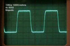
Back to grid stoppers, I remain doubtful if the results of grid stopper resistor variation would be that noticeable with amplifiers of slewy top end response, i.e -3dB at 20Khz. I obtained the results with a tube amp with a reponse -1dB at 37Khz and -3dB 68Khz. The output transformer is a multiple double 18 section Williamson design weighing 12 kilos. There is only one manufacturer willing to wind such beast. It reminds me of the Freed design used in HK. the 10Khz and 20Khz response is flawless.
richj
Attachments
- Status
- This old topic is closed. If you want to reopen this topic, contact a moderator using the "Report Post" button.
- Home
- Amplifiers
- Tubes / Valves
- Please explain grid stoppers..