TIA,
Being new to electronics and valves as well, I am willing to look ignorant ('cause I am) and ask stupid questions.
This is easy as pie to most of you, but to some of us it is confusing. I asked some questions on another thread but didn't want to hijack it. It is apparent that I am not alone in not understanding the B+Bias thing.
I am building an Aikido Linestage PreAmp with ECC802s, I purchased John Broskie's PCB kit and am almost ready to start slinging solder. I have used PSDII to design a full wave PS with minimum ripple. I have read and read but just can't quite grasp the B+ Bias to heater layout. My Transfomer has CTs on B+, 6.3V & 5V.
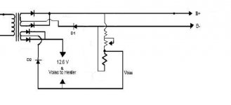
Please give me a hand with the drawing I've posted. Fire away Tell me What's wrong. Please!
Do I need D1 and D2?
What size R should I use for the safety drain from B+ to Ground?
Thanks to the Wizards of Valves for your help.
Ron
Being new to electronics and valves as well, I am willing to look ignorant ('cause I am) and ask stupid questions.
This is easy as pie to most of you, but to some of us it is confusing. I asked some questions on another thread but didn't want to hijack it. It is apparent that I am not alone in not understanding the B+Bias thing.
I am building an Aikido Linestage PreAmp with ECC802s, I purchased John Broskie's PCB kit and am almost ready to start slinging solder. I have used PSDII to design a full wave PS with minimum ripple. I have read and read but just can't quite grasp the B+ Bias to heater layout. My Transfomer has CTs on B+, 6.3V & 5V.
Please give me a hand with the drawing I've posted. Fire away
Tell me What's wrong. Please!Do I need D1 and D2?
What size R should I use for the safety drain from B+ to Ground?
Thanks to the Wizards of Valves for your help.
Ron
Attachments

Fred,
Thanks for the input.
I have removed the trim pot from the voltage divider. I misunderstood it's placement and purpose. Got it now, thanks.
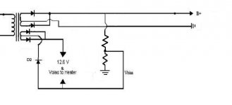
I removed the diode and leg off the B+ Center Tap, CT now goes to chassis ground. Right?
Is D2 needed? (My "Guess" is no.) As changed now, heater is floated. (not grounded to chassis)
Lookin' any better?
Thank you for the help.
Ron
Thanks for the input.
I have removed the trim pot from the voltage divider. I misunderstood it's placement and purpose. Got it now, thanks.
I removed the diode and leg off the B+ Center Tap, CT now goes to chassis ground. Right?
Is D2 needed? (My "Guess" is no.) As changed now, heater is floated. (not grounded to chassis)
Lookin' any better?
Thank you for the help.
Ron
Attachments
Hi Renron,
Sy and many contributors of this forum are simply at the level that I can only imagine. Many techniques/knowledge that are trivial to them are probably rocket science to you and me")
The new diagram is much better, now back to the heater wiring, you don't get 12.6VDC with a diode in the CT. Ignore the voltage divider and just look at the heater circuit for the moment, the voltage between the CT and the top leg is 6.3, and 6.3 between the CT and the lower leg. If you want 12.6VAC, then ignore the CT and just use the top and lower legs of the heater transformer. If you want to 12.6VDC, then the cheap way to do is to use a fullwave bridge rectification followed by a CR section, The C will bring up to approximate 16VDC, and the R is to drop it back to 12.6, or replace the R by a regulator.
In terms of safety ground, only one recommendation, use 3 wire power code and make sure the ground wire is connected to the chassis. You can search Charlie's threads, there are good discussion of how to connect the chassis ground and the circuit ground. The ground in your diagram is the circuit ground.
Sy and many contributors of this forum are simply at the level that I can only imagine. Many techniques/knowledge that are trivial to them are probably rocket science to you and me
The new diagram is much better, now back to the heater wiring, you don't get 12.6VDC with a diode in the CT. Ignore the voltage divider and just look at the heater circuit for the moment, the voltage between the CT and the top leg is 6.3, and 6.3 between the CT and the lower leg. If you want 12.6VAC, then ignore the CT and just use the top and lower legs of the heater transformer. If you want to 12.6VDC, then the cheap way to do is to use a fullwave bridge rectification followed by a CR section, The C will bring up to approximate 16VDC, and the R is to drop it back to 12.6, or replace the R by a regulator.
In terms of safety ground, only one recommendation, use 3 wire power code and make sure the ground wire is connected to the chassis. You can search Charlie's threads, there are good discussion of how to connect the chassis ground and the circuit ground. The ground in your diagram is the circuit ground.
Fred,
You Rock!
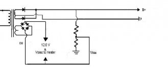
Duh! That was a stupid mistake I make with the 6.3 and 12.6 full wave. I had a test jig set up yesterday using a bridge rectifier! I confused myself. I am using a ultra fast stealth diode on the B+ side and intended to use a bridge rectifier on the heater side so I have 12.6 available............Focus Luke .......Mmmmm.....Do it you can. Humor
I'll search some of Charlie's threads. Thanks.
I'll fix the layout and repost for more wonderful critiques.
Ron
You Rock!
Duh! That was a stupid mistake I make with the 6.3 and 12.6 full wave. I had a test jig set up yesterday using a bridge rectifier! I confused myself. I am using a ultra fast stealth diode on the B+ side and intended to use a bridge rectifier on the heater side so I have 12.6 available............Focus Luke .......Mmmmm.....Do it you can. Humor
I'll search some of Charlie's threads. Thanks.
I'll fix the layout and repost for more wonderful critiques.
Ron
Hi Ron,
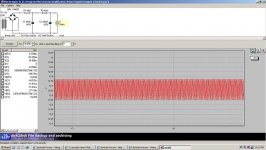
The diagram is correct, but you still don't get 12.6 VDC, Am I pain in the butt If you connect the load (tubes) right after the bridge rectifier, you can only get roughly 90% of the VAC minus the voltage dropped by 2 diodes. In this case, it will be something like 12.6 * 0.9 - 1.4 = 9.94 under load!!!! I suggest you to start with AC heater supply first and spend more time on the B+. At the current form, the B+ has no filtering at all. It is going to hum big time. If you haven't, download psud2 from www.duncanamps.com to start the PS design
The diagram is correct, but you still don't get 12.6 VDC, Am I pain in the butt
If you connect the load (tubes) right after the bridge rectifier, you can only get roughly 90% of the VAC minus the voltage dropped by 2 diodes. In this case, it will be something like 12.6 * 0.9 - 1.4 = 9.94 under load!!!! I suggest you to start with AC heater supply first and spend more time on the B+. At the current form, the B+ has no filtering at all. It is going to hum big time. If you haven't, download psud2 from www.duncanamps.com to start the PS design 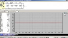
Hi Ron,
What kind of tube do you plan to use? You have the current set to 25ma which doesn't sound right. Since you are looking at 12.6V heaters, you probably have something like 12SN7 or 12A?7 or series/parallel connect of 6.3 tubes such as 6CG7 or 6922. Just one of these tube will draw much more than 25ma, and you need to multiply that by 4!!! Try 4700uF - 2ohm - 4700uF to see you can get close to 12-12.6V.
What kind of tube do you plan to use? You have the current set to 25ma which doesn't sound right. Since you are looking at 12.6V heaters, you probably have something like 12SN7 or 12A?7 or series/parallel connect of 6.3 tubes such as 6CG7 or 6922. Just one of these tube will draw much more than 25ma, and you need to multiply that by 4!!! Try 4700uF - 2ohm - 4700uF to see you can get close to 12-12.6V.
Ron,
you're indeed way off with your heater schematic. Current draw for the heaters can be taken from the datasheets, but is usually in tenths of an ampere...like 0.3A or something.
Filtering caps have to be much larger since you are dealing with lower voltages (for the heaters).
So something along the lines in the pic attched should come closer...this is for two C3G tubes for my headamp, and actual values are very close!
good luck!
Attachments
PCHW & STIXX,
Thank you both for your help and patience in teaching me!
Now that you both have pointed out where I was wrong it is easy to see. Such is the beauty of hindsite.
The Valve I will be using is ECC802s / 12au7. Heater currnet is 150mA @ 12.6V or 300mA @ 6.3V.
My Transformer puts out 5A @6.3 so current suppply is not a problem.
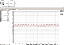
Modeling 150mA in PSUDII using STIXX schematic as a reference point (thank you) I compiled this circuit
Note: I did not take voltage drop across the Bridge into account, I'll measure it later and adjust resistor values as needed.
PSUDII is a little confusing because it states values of capacitors as mF------milli Farads, capacitor labels use the (m) to mean micro Farads. 18,000uF = 18mF in PSUDII, but looking to purchase a suitable capacitor 18mF = 18uF. This has confused me more than once.
Question: Because the heater PS capacitor is floated with 1/4 B+ Voltage but referenced to itself @~12.6V, what is the recommended voltage range?
20V? (12.6V +10% for safety) or
80V? (1/4B+ (+) 12.6V + 10% for safety)
I'm guessing 80V or 100V capacitor rating.
Thanks guys! I really appreciate the help
Ron
Thank you both for your help and patience in teaching me!
Now that you both have pointed out where I was wrong it is easy to see. Such is the beauty of hindsite.
The Valve I will be using is ECC802s / 12au7. Heater currnet is 150mA @ 12.6V or 300mA @ 6.3V.
My Transformer puts out 5A @6.3 so current suppply is not a problem.
Modeling 150mA in PSUDII using STIXX schematic as a reference point (thank you) I compiled this circuit
Note: I did not take voltage drop across the Bridge into account, I'll measure it later and adjust resistor values as needed.
PSUDII is a little confusing because it states values of capacitors as mF------milli Farads, capacitor labels use the (m) to mean micro Farads. 18,000uF = 18mF in PSUDII, but looking to purchase a suitable capacitor 18mF = 18uF. This has confused me more than once.
Question: Because the heater PS capacitor is floated with 1/4 B+ Voltage but referenced to itself @~12.6V, what is the recommended voltage range?
20V? (12.6V +10% for safety) or
80V? (1/4B+ (+) 12.6V + 10% for safety)
I'm guessing 80V or 100V capacitor rating.
Thanks guys! I really appreciate the help
Ron
Attachments
Ron,
I'm no expert either but have modelled dozens in PSUDII and actually built two psu's with good results.
Don't you have other secondary taps on your transformer? With 5A you can include a tube rectifier...
I think voltage drop across a bridge rectfier is neglectable...the more important factor here is the resistance of the secondary winding. I didn't measure, but 2ohms may be on the high side which in turn will effect your resistor value.
mF is mega-Farad?? somehow unusual term...
I'd grab two 22000uF/25V since you are still heating your tubes with 6.3V and not 60V or something. I can't put the explanation in scientific terms (at a lack of words here being german ) but referencing the heaters to B+ of course doesn't change heater voltage.
best,
Oliver
I'm no expert either but have modelled dozens in PSUDII and actually built two psu's with good results.
My Transformer puts out 5A @6.3 so current suppply is not a problem
Don't you have other secondary taps on your transformer? With 5A you can include a tube rectifier...
Note: I did not take voltage drop across the Bridge into account, I'll measure it later and adjust resistor values as needed.
I think voltage drop across a bridge rectfier is neglectable...the more important factor here is the resistance of the secondary winding. I didn't measure, but 2ohms may be on the high side which in turn will effect your resistor value.
18,000uF = 18mF in PSUDII, but looking to purchase a suitable capacitor 18mF = 18uF.
mF is mega-Farad?? somehow unusual term...
I'd grab two 22000uF/25V since you are still heating your tubes with 6.3V and not 60V or something. I can't put the explanation in scientific terms (at a lack of words here being german
) but referencing the heaters to B+ of course doesn't change heater voltage.best,
Oliver
Stixx,
Sehr Dank, My German is not good, sorry.
But Thank, Thank, Thank you.
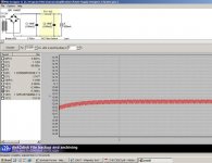
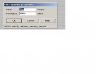
In PSUDII the (m) for size of capacitors is milli, not Mega. see below,
I am having enough trouble understanding what I am doing without adding a rectifier valve too.
Obviously this is my first Preamp - electronics project.
Ich möchte ein Bier trinken mit Ihnen (from Google translate)
Ron
Sehr Dank, My German is not good, sorry.
But Thank, Thank, Thank you.
In PSUDII the (m) for size of capacitors is milli, not Mega. see below,
I am having enough trouble understanding what I am doing without adding a rectifier valve too.
Obviously this is my first Preamp - electronics project.
Ich möchte ein Bier trinken mit Ihnen (from Google translate)
Ron
Attachments
Hi Ron,
You mentioned that your trafo has 2 x 6.3V secondaries. So, the 5A rating is the sum of the 2, correct? Or, it is 5A each Either case, you will need to wire them in series to get 12.6V, so the current rating will be the same. 4 x 12AU7 in 12.6V only consume 0.6A total, you have plenty to spare. If you want reasonably good heater supply, use a LM317T to regulate the voltage, 0.6A is well below it's 1.5A limit. You will find plenty references here or in the web on how to use LM317T. If you don't want to get too complex for the time being, just use CRC where C=4700uF (as Oliver said, 25V rating is good enough) and R=3 or 4 ohms (5W). Later, you can upgrade the RC section to the LM317T circuitry. For 12AU7, connect the ground of the heater supply to 1/4 of the B+ should be good.
You mentioned that your trafo has 2 x 6.3V secondaries. So, the 5A rating is the sum of the 2, correct? Or, it is 5A each
Either case, you will need to wire them in series to get 12.6V, so the current rating will be the same. 4 x 12AU7 in 12.6V only consume 0.6A total, you have plenty to spare. If you want reasonably good heater supply, use a LM317T to regulate the voltage, 0.6A is well below it's 1.5A limit. You will find plenty references here or in the web on how to use LM317T. If you don't want to get too complex for the time being, just use CRC where C=4700uF (as Oliver said, 25V rating is good enough) and R=3 or 4 ohms (5W). Later, you can upgrade the RC section to the LM317T circuitry. For 12AU7, connect the ground of the heater supply to 1/4 of the B+ should be good.In PSUDII the (m) for size of capacitors is milli, not Mega. see below,
haha, true...it occurred to me a few minutes after I posted, but I couldn't edit my post anymore.
Obviously this is my first Preamp - electronics project.
You'll get there, no doubt! Three years ago a schematic basically was some sort of egyptian artwork to me...
I learned from reading, and more reading...ch möchte ein Bier trinken mit Ihnen (from Google translate)
Prost - - - - Cheers!!
Oliver
I must be learning!!!!
I let the magic smoke out of the Bridge rectifier yesterday
I looked at the transformer and it is (1) 6.3V CT...not (2) 6.3V secondaries... .....I must be learning......SOMETHING.....??
After I finished laughing, I figured out what I did and DOH! Newbie me, I twisted both legs of the CT 6.3 to the + of the bridge and ran the CT to the - side......and POOF! Pretty blue smoke , blew the fuse too! LOL .....I must be learning.
Oliver, Prost! Thanks for the words of encouragement!
I realize that my transformer has 6.3V CT, so unless I use a voltage doubler circuit I will have to use 6.3V for Heater Supply.
I know A/C is OK, but I'd prefer DC heaters.
Fred, Thanks for the suggestions with the LM317T, I'll go with that after the FW rectifier with CT.
Thanks Very much guys!
Ron
I let the magic smoke out of the Bridge rectifier yesterday
I looked at the transformer and it is (1) 6.3V CT...not (2) 6.3V secondaries...
.....I must be learning......SOMETHING.....??After I finished laughing, I figured out what I did and DOH! Newbie me, I twisted both legs of the CT 6.3 to the + of the bridge and ran the CT to the - side......and POOF! Pretty blue smoke
, blew the fuse too! LOL .....I must be learning.Oliver, Prost! Thanks for the words of encouragement!
I realize that my transformer has 6.3V CT, so unless I use a voltage doubler circuit I will have to use 6.3V for Heater Supply.
I know A/C is OK, but I'd prefer DC heaters.
Fred, Thanks for the suggestions with the LM317T, I'll go with that after the FW rectifier with CT.
Thanks Very much guys!
Ron
Hey, Ron, we all had those daysRenron said:I must be learning!!!!
I let the magic smoke out of the Bridge rectifier yesterday
I looked at the transformer and it is (1) 6.3V CT...not (2) 6.3V secondaries...
After I finished laughing, I figured out what I did and DOH! Newbie me, I twisted both legs of the CT 6.3 to the + of the bridge and ran the CT to the - side......and POOF! Pretty blue smoke
Oliver, Prost! Thanks for the words of encouragement!
I realize that my transformer has 6.3V CT, so unless I use a voltage doubler circuit I will have to use 6.3V for Heater Supply.
I know A/C is OK, but I'd prefer DC heaters.
Fred, Thanks for the suggestions with the LM317T, I'll go with that after the FW rectifier with CT.
Thanks Very much guys!
Ron
 No guts, no glory, right
 When you twisted the two legs of the 6.3, you effectively shorted the secondary. Good that you had the fuse in place. Before you work on the doubler, measure the AC of the 2 legs just to make sure it is 6.3. Also, tape the CT to void accidentally shorting. You are not likely to use it.
Have fun!!
- Status
- This old topic is closed. If you want to reopen this topic, contact a moderator using the "Report Post" button.
- Home
- Amplifiers
- Tubes / Valves
- Help with Aikido B+ Bias layout