after modeling a preamp design using submini 6BF7 tubes (actually used 12AU7 in the sim), and prototyping it with the tubes, here's the results:
SIM:
overall gain : 20
input level to clipping: 500mV
distortion: 0.2%THD
current set resistor for CCS 1.5k
PROTO:
overall gain: 60
input level to clipping: 100mV
distortion: not tested yet
current set resistor for CCS 10k
so there is a bit of difference between the 12AU7 and 6BF7 as far as gain, etc...... but it's close enough to "ballpark" a design.
Attachments
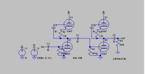
the upper tubes are current source loads instead of plate resistors. and yes, only 12V. these tubes are rated 100V max plate voltage, and i will probably make a version that uses more voltage, maybe a rack mount preamp. like i said, i have a surplus of 12V wall warts, and they are commonly available at music stores, so i went with a voltage that won't be difficult to find. it also simplifies the filament supply problem, the filaments to the tubes are wired in series. the other option was to run the preamp at 30V, and use a LM7805K for the filament supply (yes the filaments work well enough at 5V).....
Hey unclejed613 you need to replace those caps on the upper tubes (your current sources) with small resistors or a short to provide a path for grid current to flow.
Honestly speaking from a voltage headroom perspective you might be a little better off with a transistor based ccs in place of the tubes.
You could also use a charge pump based voltage doubler to get roughly 24V for your plates - current would be low enough this would work well.. Use a comparator with a totem pole output as a square wave oscillator and use a 1/2 wave doubler referenced to the +12V to get your 24V..
since so many guitarists like tube fuzz, i decided to keep it the way it is...... actually, i omitted the caps, but forgot to remove them from the schematic. it works either way....... the finished product will have markings on the input control approximating the "clean" range and "fuzz" range. it has a nice gradual transition from clean to fuzz. the first visible signs of distortion are a slight rounding of the positive side of the waveform, gradually flattening out as the tubes clip. should be a very smooth, controllable transition. once i get it in a box, i'll get a chance to try it with a guitar. except for heat, i don't see a problem building this into a guitar, either. i have several ideas on how to dissipate the heat, one of them being to mount the tubes in an aluminum block.
got a chance to sound test it today with a guitar and a SS amp...... makes a great clean preamp at low to medium gain, and has a smooth distortion sound with the gain from medium to full.
one of the guitarists that tried it liked the preamp's "touch" (being able to go from clean to fuzz just by changing playing style).
mod opinion? i know this thread started out strictly tube, but should i have continued this in Musical Instruments?
one of the guitarists that tried it liked the preamp's "touch" (being able to go from clean to fuzz just by changing playing style).
mod opinion? i know this thread started out strictly tube, but should i have continued this in Musical Instruments?
- Status
- This old topic is closed. If you want to reopen this topic, contact a moderator using the "Report Post" button.
- Home
- Amplifiers
- Tubes / Valves
- 12v 6BF7 preamp design tested