Hello all...
Does anyone else have a Mr Liang 845 amplifier and have the same problem as myself and my mate Dave. When we first got these amplifiers they were highly musical with bouncy bass underpining the music.... We did some tube rolling and clarity improved, still maintaining that musicallity.
However about 100 hours use has now passed and both Mr Liang 845 's have gone quite thin and non musical sounding ? This is with 845 original and 845B's
We have tried Lampizator's new circuit which uses 6sl7 / 6sn7 tubes as a replacement driver stage and that bring back the original musicallity. Lukasz says this is because Liang uses Pentode's instead of Triode's.
However I do not want to give up on Mr Liang's original tubes (6ac7 and 5881) and design if it can be brought back from the 'brink'...
Anyone any input / advise.
Regards
David
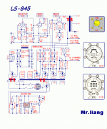
Circuit here...
http://www.triode-systems.com/uploads/photos/120.png
Does anyone else have a Mr Liang 845 amplifier and have the same problem as myself and my mate Dave. When we first got these amplifiers they were highly musical with bouncy bass underpining the music.... We did some tube rolling and clarity improved, still maintaining that musicallity.
However about 100 hours use has now passed and both Mr Liang 845 's have gone quite thin and non musical sounding ? This is with 845 original and 845B's
We have tried Lampizator's new circuit which uses 6sl7 / 6sn7 tubes as a replacement driver stage and that bring back the original musicallity. Lukasz says this is because Liang uses Pentode's instead of Triode's.
However I do not want to give up on Mr Liang's original tubes (6ac7 and 5881) and design if it can be brought back from the 'brink'...
Anyone any input / advise.
Regards
David
Circuit here...
http://www.triode-systems.com/uploads/photos/120.png
Attachments
Here are the voltages
I have to say it did not sound as bad last night. It was a little fuller sounding although still not as good as when new. Normally when tube and caps run in they usually sound better ?
I measured the voltages and they are as shown.
BTW, first tube is a 6ac7, 2nd stage is a 6L6
I am thinking of trying some Valve Art 6550A in place of the 6L6, the power tx can handle the heater demand at 2.5A per side.
Regards
David
Attachments

Mr Liang sound
Hi All
I also have a Mr Liang 845, and it seems to be behaving in a similar way to yours Swamp.I have changed coupling caps to obligatto same as you , replaced input stage tubes and changed output tubes to 845b.I thought the amp as recieved from Mr liang was one of the best capable of driving a rythm and making you want to get up and dance along with the music,but to me it always sounded a touch dirty or not quite right,thats the reason I made the mentioned changes.I must admit that sometimes late at night it sounded quite good, but next day back to not quite right.I saw the mods carried out by lampizator guy,and having built one of his tube output stages for my cd94,I thought I would give it a try,the results are a far better than I expected rightness to the sound.I cant explain why the sound is so much better butLampizator says its because he uses triodes and Mr Liang uses pentodes, but I cant help wondering if Mr Liang has not used pentodes as best he could,his circuit looks abit long winded to me.Hope this helps .
David Robert
will these work ?
Since no one has replied with any ideas may be someone can tell me if these will work...
1) take the signal off the anode of the 2nd stage (6l6) rather than the cathode. I have never been too keen on cathode followers. Zout will be higher though, will this work ? Simple case of move the 0.47 cap ?
2) and/or... remove stage 1 and the volume pot and feed signal in on pin 5 of the 6l6 making it a pure power amp.
Regards
David
Re: will these work ?
You can remove the volume pot, but you still need the first stage as it provides all of the voltage gain prior to the output tube. Reconfiguring to get rid of the cathode follower is more problematic.
One of the big problems with some versions of this design is that the cathode follower runs at really low currents. This design seems to run at about 4mA, frankly it seems to me that this is too low for good linearity with the 6L6. I would try modifying to use a 6J5 or similar at about 5 - 6mA which would probably sound a lot better. (Just make sure you don't exceed the maximum voltage ratings of the 6J5 in the redesign.)
You might also take a look at the quality of the coupling caps and electrolytics in the signal path. Replacing a few of these with better parts might help.
FWIW I would be surprised if the 6550 wasn't even worse, this circuit just doesn't run the CF at a reasonable quiescent current for any power tube.. I would consider the KT66 a slightly better choice, but not a good one. (see above)
Overall I wouldn't call this a very good design, but the chassis is nice, and the iron apparently acceptable so it should make a good vehicle for mods. I don't see any reason to keep the original design if you have already identified a mod that sounds significantly better.
In terms of the sound quality I suspect you have gotten used to the good aspects of its performance and are now noticing the warts.. Happens to all of us regardless of the merits of the device in question.
swamp said:Since no one has replied with any ideas may be someone can tell me if these will work...
1) take the signal off the anode of the 2nd stage (6l6) rather than the cathode. I have never been too keen on cathode followers. Zout will be higher though, will this work ? Simple case of move the 0.47 cap ?
2) and/or... remove stage 1 and the volume pot and feed signal in on pin 5 of the 6l6 making it a pure power amp.
Regards
David
You can remove the volume pot, but you still need the first stage as it provides all of the voltage gain prior to the output tube. Reconfiguring to get rid of the cathode follower is more problematic.
One of the big problems with some versions of this design is that the cathode follower runs at really low currents. This design seems to run at about 4mA, frankly it seems to me that this is too low for good linearity with the 6L6. I would try modifying to use a 6J5 or similar at about 5 - 6mA which would probably sound a lot better. (Just make sure you don't exceed the maximum voltage ratings of the 6J5 in the redesign.)
You might also take a look at the quality of the coupling caps and electrolytics in the signal path. Replacing a few of these with better parts might help.
FWIW I would be surprised if the 6550 wasn't even worse, this circuit just doesn't run the CF at a reasonable quiescent current for any power tube.. I would consider the KT66 a slightly better choice, but not a good one. (see above)
Overall I wouldn't call this a very good design, but the chassis is nice, and the iron apparently acceptable so it should make a good vehicle for mods. I don't see any reason to keep the original design if you have already identified a mod that sounds significantly better.
In terms of the sound quality I suspect you have gotten used to the good aspects of its performance and are now noticing the warts.. Happens to all of us regardless of the merits of the device in question.
swamp said:I was considering driving it with a pre-amp if that first stage was removed.
If R106 is lowered to 20 - 25K then that would increase the current on that cathode follower.
Does anyone have any links to recommended 845 schematics worth building ?
Thanks
David
Hi David,
You would need a pre-amp capable of swinging more than 240Vpp cleanly to drive the 845 to full power so you really need that first driver stage.
Yes reducing R106 will increase the current in that cathode follower, but might also result in fried power transformer winding depending on the rating of that particular winding. I would think no less than 20 - 30mA would be required to get the 6L6 up high enough on the transconductance curve to justify its use, and this is clearly a bad idea if you don't know the current rating of that winding.
You could use a 6J5 in the first stage and a 6SN7 configured as an srpp running at about 8mA in the second stage and this ought to work pretty well.
Google for links to 845 amplifier designs, there are plenty out there.
kevinkr said:
Hi David,
You would need a pre-amp capable of swinging more than 240Vpp cleanly to drive the 845 to full power so you really need that first driver stage.
Yes reducing R106 will increase the current in that cathode follower, but might also result in fried power transformer winding depending on the rating of that particular winding. I would think no less than 20 - 30mA would be required to get the 6L6 up high enough on the transconductance curve to justify its use, and this is clearly a bad idea if you don't know the current rating of that winding.
You could use a 6J5 in the first stage and a 6SN7 configured as an srpp running at about 8mA in the second stage and this ought to work pretty well.
Google for links to 845 amplifier designs, there are plenty out there.
Hi Kevin...
I dropped the cathode R to 24K WW and it sounds much better with more weight. I am sure the tx can cope since it has unused heater taps for feeding a 300B as a driver. The same HT used to drive the 300B is being used to drive the 6l6 in this case, Mr laing uses the same transformers.
Current is now 5.5mA, still not up there but better than 3mA as previous !!
Thanks for the pointer.
Regards
David
David
swamp said:
Hi Kevin...
I dropped the cathode R to 24K WW and it sounds much better with more weight. I am sure the tx can cope since it has unused heater taps for feeding a 300B as a driver. The same HT used to drive the 300B is being used to drive the 6l6 in this case, Mr laing uses the same transformers.
Current is now 5.5mA, still not up there but better than 3mA as previous !!
Thanks for the pointer.
Regards
David
David
I think you are probably safe at this or even a significantly higher current level, but I wouldn't go over 10mA without knowing the winding's rating. Just because there are unused filament windings does not necessarily mean that it is safe to draw a lot more power from this winding - you have to take into account the winding resistance and the potential rise in winding temperature of that specific winding. Even though the overall power consumed may be well within the transformer's overall rating it is quite possible to overload a single winding to the extent that it fails due to thermally induced insulation failure. I have had this problem with dodgy custom transformer designs where all windings were run within their ratings, but a particular winding was run near its design current rating.
Thanks Kevin....
I was going to try 15K but the resistors I have in my parts box were too low power rating.
I stuck to the 24K and it is vastly better soundwise. Very solid, deep bass and fleshed out now, just like I thought the 845 should be. Like you said, that 6l6 was hardly being driven.")
I was going to try 15K but the resistors I have in my parts box were too low power rating.
I stuck to the 24K and it is vastly better soundwise. Very solid, deep bass and fleshed out now, just like I thought the 845 should be. Like you said, that 6l6 was hardly being driven.
I have one of these, the version with the 300B cathode followers driving the 845 grids. It's a GREAT sounding amp. A giant killer. If you can find one, BUY IT. (That is, if you're getting into SET amps) Of course, some $5,000 amp probably sounds better. But these tend to go for $900~$1200 used, and at that price- a GREAT SET amp. Be sure to put a pair of Shuguang 845B tubes in it, they sound much better than the stock 845's and note that the 845B's sound nearly as good as NOS RCA's (about 90% compared to RCA NOS = 100%; no kidding)
You can also roll the input tubes some.
But anyway, GREAT output transformers, good power supply; decent topology.
You can also roll the input tubes some.
But anyway, GREAT output transformers, good power supply; decent topology.
Can anyone tell me the bias range set by the bias pots for the 845 grids....and what is the nominal setting.??
Thanks
JB
Set it to 90 mA as indicated on the grid current meters. That's the "factory spec."
Mr Liang sounds like chinese character I'm chinese student login in just now,Who is liang?have you mesured the 110V~votage?is it that normal?The votage are as shown where is the plate votage of 845?only 845 or all of tubes?I have to say it did not sound as bad last night. It was a little fuller sounding although still not as good as when new. Normally when tube and caps run in they usually sound better ?
I measured the voltages and they are as shown.
BTW, first tube is a 6ac7, 2nd stage is a 6L6
I am thinking of trying some Valve Art 6550A in place of the 6L6, the power tx can handle the heater demand at 2.5A per side.
Regards
David
to change the 6j4 to a 6sj7. remove R102 and replace with a jumper wire. replace R101 with a 820 ohm resistor.
replace 100K volume control with a 1M control. wiper to the rca jack positive, top of the control to pin 4 of the 6sj7.
replace r104 with a 330K resistor.
c102 needs to be connected between R104 and pin 5 of the 6sj7; this capacitor is wrong in the original schematic.
remove c101, that capacitor seems to have been added because of the extreme impedance mismatch. bypass cap should not be needed if the circuit is set up correctly.
the input circuit is incorrect on the original schematics there is a great input impedance mismatch. needs to be a 250K control, but a 6sj7 sounds better. 6j4 wear out sonically quick too and get very micro phonic.
Hi!
Besides the weaknesses others have already mentioned. If the plate voltage in the schematic at the input tube is correct (100V) that means that it cannot even provide enough voltage swing to drive the output tube to full power. It does not have no headroom, it even has negative headroom.
That means the input tube completely dominates the sound of the amp. For marginal designs it is typical that the sound keeps changing. Minor shifts in op points, which can be caused by mains voltgae variations can have major impact on the sound.
The questions is if it makes sense to try to modify such an incompetent design. Who knows which other weaknesses are hidden.
If you want to keep this amp, get someone experienced to redesign the frontend and also have a look at other aspects of the amp, for example voltage and current rating of parts. Some chinese amps are known for underated parts.
Best regards
Thomas
Hi!
Besides the weaknesses others have already mentioned. If the plate voltage in the schematic at the input tube is correct (100V) that means that it cannot even provide enough voltage swing to drive the output tube to full power. It does not have no headroom, it even has negative headroom.
That means the input tube completely dominates the sound of the amp. For marginal designs it is typical that the sound keeps changing. Minor shifts in op points, which can be caused by mains voltgae variations can have major impact on the sound.
The questions is if it makes sense to try to modify such an incompetent design. Who knows which other weaknesses are hidden.
If you want to keep this amp, get someone experienced to redesign the frontend and also have a look at other aspects of the amp, for example voltage and current rating of parts. Some chinese amps are known for underated parts.
Best regards
Thomas
I think you are not correct in your analysis of the circuit. But then I have the actual amplifier in front of me and you are just speculating.
There's plenty of voltage swing on the grid of the 845 from the 300b that drives it in my Mr. Liang 845. There's no problem driving the amp to it's rated output of 22 watts. Driving it harder than that results in the final stage clipping, but the drive to the grid is NOT clipped, so it's clear that the input & driver stage have sufficient headroom.
The parts in the amp are all of excellent quality. Again, rather than just say things based on my imagination, I am at an advantage because I have the actual amplifier here to investigate and can speak from the facts - not from vague speculation.
I'd be curious to learn what you thought of the amp when you heard it- because, surely, someone who speaks with such authority about the quality of an amplifier MUST have actually auditioned the unit in question....no?
By the way, I haven't noticed any sonic changes that come and go over time with this amp; I have the version using 300B driver tubes, not 6L6's, so it's a somewhat different amp, so maybe that's a factor, I really don't know.
Last edited:
- Status
- This old topic is closed. If you want to reopen this topic, contact a moderator using the "Report Post" button.
- Home
- Amplifiers
- Tubes / Valves
- Mr Liang 845 Sound :(