Instead of having to use a separate winding for each DHT I was thinking about building modular "off-line" switching supplies. The outputs are isolated from the inputs so a single AC supply is all thats needed. Heck they could even be run straight from the mains supply.
Most of the offline switching chips operate at 100Khz or less but I would try for at least 1Mhz. Speeds in the Mhz range are becoming more common now. So does this sound like a good idea?
Most of the offline switching chips operate at 100Khz or less but I would try for at least 1Mhz. Speeds in the Mhz range are becoming more common now. So does this sound like a good idea?
computer monitors and tv's have been running the crt filaments from the flyback for a very long time. there was a time when tv's used the main filament supply, but that was discontinued in the '70's and '80's.......
with switching supplies, you reference your regulation through an optoisolator, usually sensing from your highest secondary voltage (or just pick one secondary voltage you will always use, and sense from that one. overdesign the primary side. then you can add windings and rectifiers on the secondary to get whatever voltages you need....... SMPS can be very flexible. your frequency limitation is determined mostly by the speed of your rectifiers. also schottky diodes are rarely rated at more than 60V PIV.
with switching supplies, you reference your regulation through an optoisolator, usually sensing from your highest secondary voltage (or just pick one secondary voltage you will always use, and sense from that one. overdesign the primary side. then you can add windings and rectifiers on the secondary to get whatever voltages you need....... SMPS can be very flexible. your frequency limitation is determined mostly by the speed of your rectifiers. also schottky diodes are rarely rated at more than 60V PIV.
All of the off the shelf SMPS chips produce square waves. Experimentation with square waves in the 250 KHz range on DHT filaments produced some IMD distortion products that fell back into the audio range. The resulting sound had an unusual quality that was not easily identified, but all agreed that it was not good.
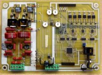
Pete's circuit produces reasonable sine waves by adding capacitance across the transformers primaries. This reduces the efficiency by forcing the mosfets to operate in the linear region. This obviously works (as he has proven) at low power levels but may cause unexpected mosfet death syndrome at higher power levels. Instant mosfet explosion will result if tried in an off line converter (as me how I know this).
The easy solution is to use DC on the filaments, but that makes this whole idea redundant. It is possible to "modulate" an SMPS that operates at a high frequency (say 1 to 2 MHz) with a sine wave at a lower frequency (say 100 to 200 KHz). This is the avenue that I am currently exploring.

Tubelab what I was thinking is a simple switcher with a clean DC output and a wide range AC input. So you could buy a cheap transformer and feed as many isolated modules as you want. No more custom transformers with a half dozen secondaries.
Fairchild has a good offline smps simulator http://www.fairchildsemi.com/whats_new/offline_smps_toolkit.html
The only problem that might come up is needing a custom transformer for the switcher
Fairchild has a good offline smps simulator http://www.fairchildsemi.com/whats_new/offline_smps_toolkit.html
The only problem that might come up is needing a custom transformer for the switcher
Curious, I never thought of it that way. If I were to use seperate wires off the B+ capacitor to each tube, I could balance mismatched tubes with a wirewound dropping resistor or 5w pot? Plate voltage being off a bit being less a sin than unbalanced current in the output transformer.
tubelab.com said:This reduces the efficiency by forcing the mosfets to operate in the linear region.
Actually it's not linear - it works as a zero-voltage-switched resonant converter, with each side turning on for maybe 30-45 degrees of the sine wave. So efficiency is OK. The biggest problem I had was actually the buck converter section that regulates output voltage, with the diode getting hot. A synchronous design would be better, or a bigger diode! Peak circulating currents here are wicked high, so that limits output power. It would be better to start with a higher input voltage, and custom-wind a transformer.
astouffer said:Tubelab what I was thinking is a simple switcher with a clean DC output and a wide range AC input. So you could buy a cheap transformer and feed as many isolated modules as you want. No more custom transformers with a half dozen secondaries.
I've used isolated DC-DC converters several times for DHT filament supplies. It does allow you to use a single supply to feed several isolated filaments. They seem to work pretty well, though they do tend to induce some HF junk.
My 813 amps (http://www.pmillett.com/813_se_triode_amps.htm) generates 48VDC from a conventional linear supply then uses DC-DC converters to get the 10V for the 813 filaments. Another amp I have running now does a similar thing, starting with +/24V (from a SMPS) to generate low voltage for filaments in a stereo amp.
Pete
astouffer said:The only problem that might come up is needing a custom transformer for the switcher
You can get cores from cws bytemark in low qty. A good book like
Switching Power Supply Design by Pressman contains a good magnetics design section.
It's not too too hard with a bit of practice and research.
It's not too too hard with a bit of practice and research.
It may not be too hard, but I have a big pile of toasted mosfets that says that its not too easy either.
A few words of caution / warning:
When working with higher powered SMPS circuits cover the PCB with a piece of clear Lexan on initial power up. Mosfets can explode without warning, often violently. I have even had the magnetics shatter.
Capacitors must be low ESR and rated for SMPS use. Cheap surplus caps will explode. You can't use an ordinary silicon diode, they will melt due to recovery time. Schottkeys or "fast recovery" diodes are required.
Discarded computer power supplies are good sources for parts. The magnetics are often about right for filament supplies.
Bad things happen when you drag a car battery into your work room and hook it up to a circuit (experience speaks). I now have a 0 to 20 volt, 0 to 50 amp power supply. It will still make mosfets vanish, but the chance of fire is far lower than a car battery! When using a bench supply for testing, current limiting is your friend. Setting the current limit too low can cause the switcher to start up improperly resulting an a dead mosfet.
When working with off line supplies the obvious isolation transformer is required. In addition, build a fixture that allows some ordinary incandescent light bulbs to be wired in series with the line input. Use a low wattage bulb on initial power up, and a higher wattage bulb for testing. The bulbs can be bypassed as circuit confidence increases. These may not save your mosfets but will keep the schrapnel to a minimum.
When working with something really unique like a DSP controlled agile dual buck converter that runs off of a 450 volt supply, be prepared to sacrifice a lot of parts to the fire gods. Lexan safety shield required. Loose the low ESR motor run caps across the source supply. They can dump enough energy into a mosfet to make all but the leads dissappear.
1KV, 5 amp mosfets are not cheap, therefore they like to blow up easilly. 4.7 ohm 1/4 watt resistors inserted in series with the drain will vanish from the PC board often saving the $5 mosfet. Again Lexan is your friend.
Attachments
Actually it's not linear - it works as a zero-voltage-switched resonant converter, with each side turning on for maybe 30-45 degrees of the sine wave. So efficiency is OK.
Pete, I studied your schematic a bit further. I had not looked at the UC3872 chip or any lamp ballast IC yet. I think that I will get a few to experiment with next time I order parts.
I have been making tube amps for a long time, but am just getting started with SMPS's. So far, I have made quite a few dead parts and a few working circuits. A tube will warn you with a red glow when it is unhappy. An off line supply will just go bang!
I did make a sine wave HF power supply for 811A's a few years ago. It was completely linear however, basically a 25 watt amplifier that ran at 100 KHz. The resulting amplifier sounded pretty good, but the mosfets got almost as hot as the 811A.
- Status
- This old topic is closed. If you want to reopen this topic, contact a moderator using the "Report Post" button.
- Home
- Amplifiers
- Tubes / Valves
- A new DHT power supply idea