This thread on that amp may help you.
http://www.diyaudio.com/forums/class-d/63315-autocostuire-fenice-20a-hiss-problems-2.html
http://www.diyaudio.com/forums/class-d/63315-autocostuire-fenice-20a-hiss-problems-2.html
This thread on that amp may help you.
http://www.diyaudio.com/forums/class-d/63315-autocostuire-fenice-20a-hiss-problems-2.html
Hey thanks for that, yep someone there mentions fitting 0.1u caps
")
Thanks that's useful to know, will make sure the writing on the caps ends in the direction of those wire connectors. Many thanks
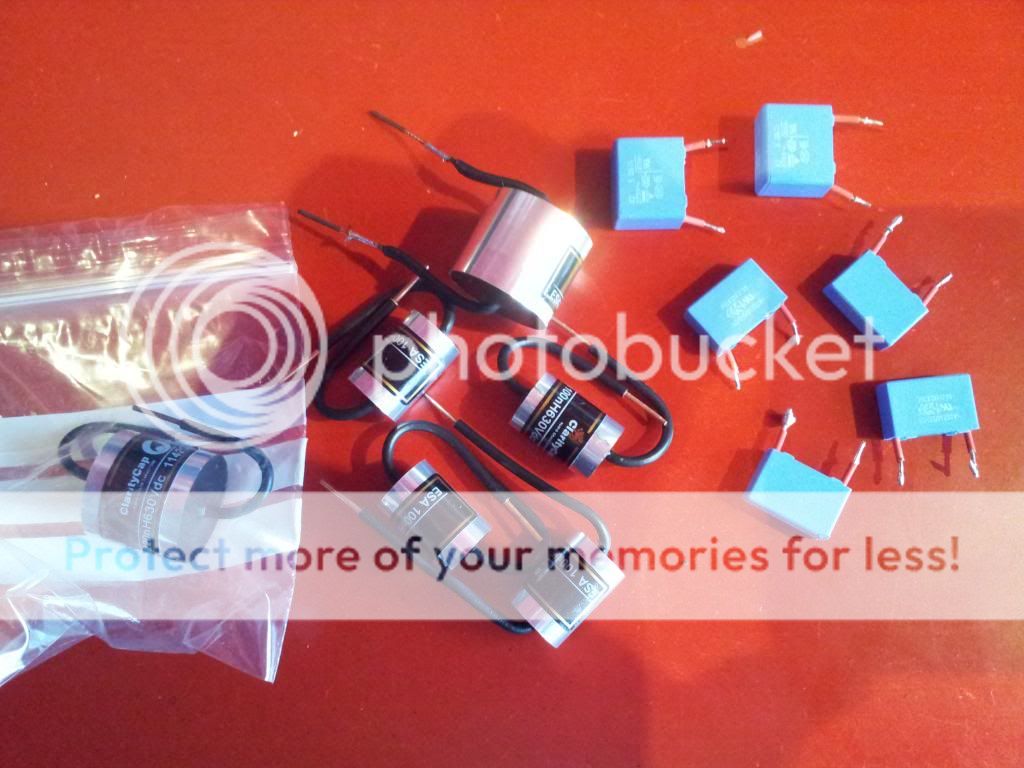
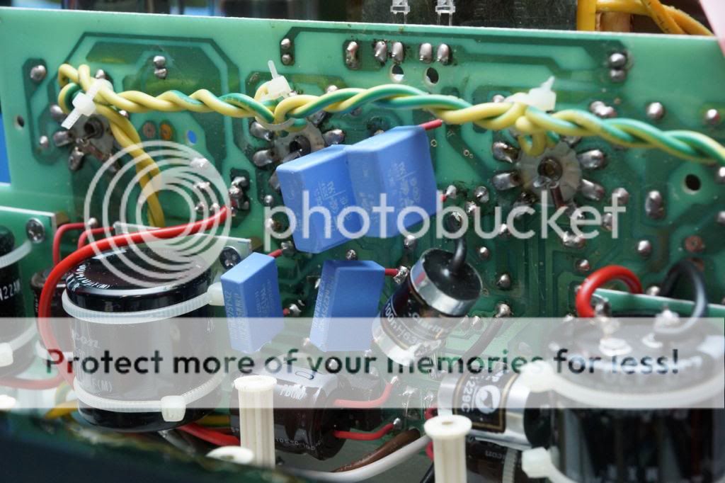
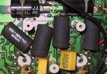
The caps have arrived but the label wraps around !
(CCESA-0009)- 0.068uF 630Vdc Claritycap ESA Range polypropylene Hifi Collective
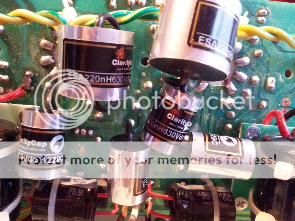
Yikes! I couldn't do that, the caps look far too big but worth it I suppose if you get any improvement. Are the outsides covered with conductive foil? Just wondering if one of the sleeves on the right channel capacitors may be touching a heater wire and inducing hum into the signal. A wild guess I know but it would more likely be the 220nF. If the outsides are conductive, I would have thought a good idea would be to have a connection available to the outer covering so it could be grounded and act as a screen similar to the capacitors used in the Quad amplifiers. I get the impression that those are very much sought after.
Ohhhh Les, man what a treat this little adventure has been regardless of the hum. Sonically very smooth and effortless, Gone is the GLARE, bags more detail with noticeable 3D. Bass dips deep and is far more punchy. And this, with only half an hour of burn in.
These caps for the cash rock. ClarityCap ESAs ;0
These caps for the cash rock. ClarityCap ESAs ;0
Next stage is bypassing the volume pot and the input selector. Don't need these as I only have the one source with its own remote volume (Audiolab M-DAC).
My question being will this improve the sonics as at the moment the signal is running through two volume controls ?
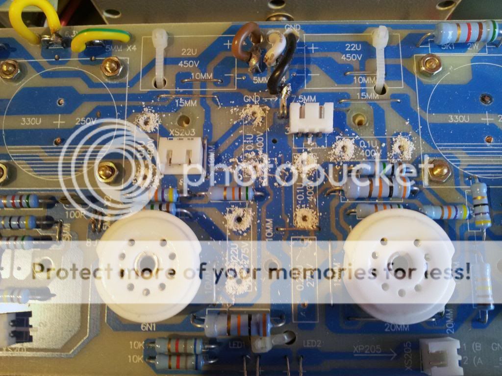
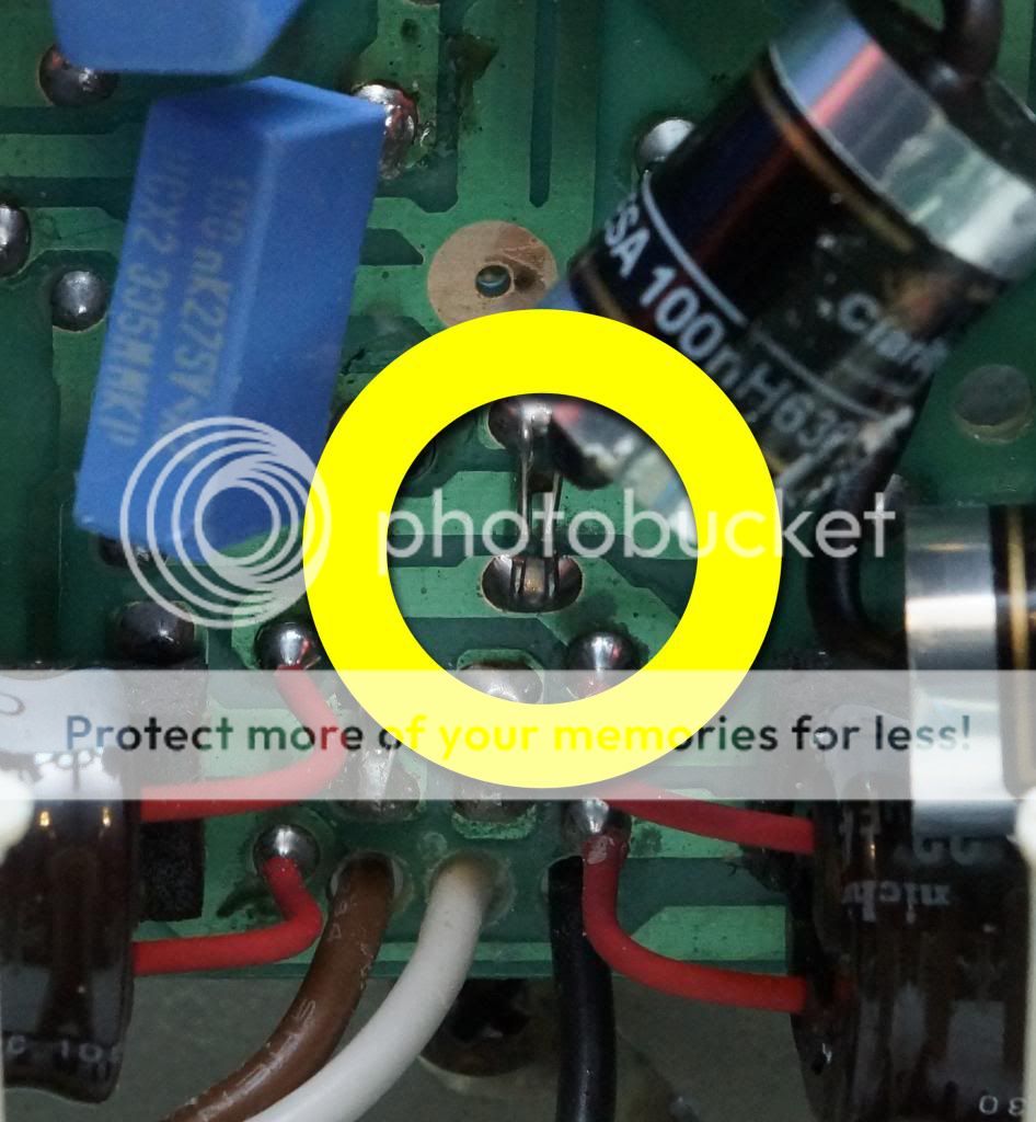
Can someone also let me know if I have got the wiring correct please ! I am assuming that all I need do is run the L + R signals from the rear input plate to the front pre amp board here:
My question being will this improve the sonics as at the moment the signal is running through two volume controls ?
Can someone also let me know if I have got the wiring correct please ! I am assuming that all I need do is run the L + R signals from the rear input plate to the front pre amp board here:
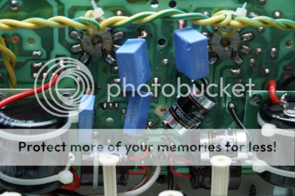
Physically large caps can pick up more hum and noise than smaller ones of the same value, because they have larger stray capacitance to nearby objects such as AC wiring and radio transmitters.Got the ClarityCap ESA's fitted, but have a low hum on the right channel. Any ideas ?
Physically large caps can pick up more hum and noise than smaller ones of the same value, because they have larger stray capacitance to nearby objects such as AC wiring and radio transmitters.
I see, pity about that, replaced caps on amps before in tighter places than this without any problems. Have moved them a bit only to make it worse
Any suggestions ?
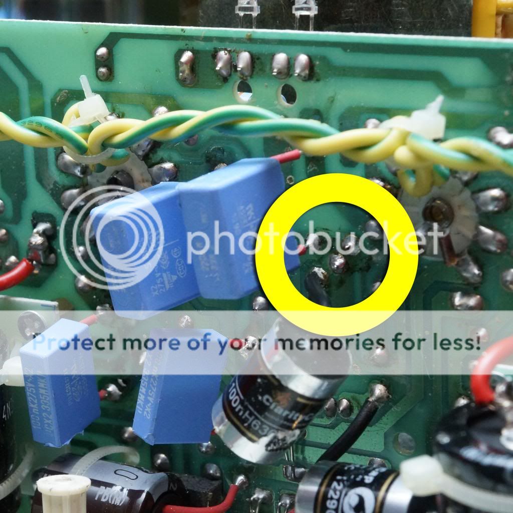
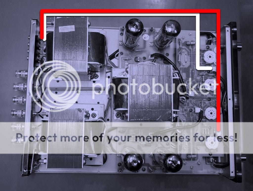
Pull the phase splitter out - is the hum still there? You need to try some simple things that can enable you to zero in on where the problem lays. Will have a look to see if I have any stock photo that show what's on these pads bu the shots are normally from far away to take in the whole board.
lol - the inner most two small ones are the phase splitters. the one to the left (V2) is the left hand and the next one V3 is the right hand channel. Let the amp cool before pulling them, not just because the valve is still hot but the crackle will pull your cones out, well probably not but it will be uncomfortable.
Check your bias voltages are around 0.35V. I assume you have tried the valve swap over technique but it's always a good thing to check the bias is ok first. Excess current through the valve will produce hum but normally you see other fireworks at this stage or at least cherry red anode plates.
lol - the inner most two small ones are the phase splitters. the one to the left (V2) is the left hand and the next one V3 is the right hand channel. Let the amp cool before pulling them, not just because the valve is still hot but the crackle will pull your cones out, well probably not but it will be uncomfortable.
Ok, think I get your drift: Remove the two inner front valves then turn the amp on ? Not doing anything until I get a confirmation !
- Home
- Amplifiers
- Tubes / Valves
- Yaqin mc10L