kuroguy said:more than likely, it gets hotter because it has less airflow around it.
Cannot agree with that, the pot was originally a sealed box so no air flow at all and the only cooling was by radiation from the transformer to the outer case. The new air vent at least allows the hot air to move more freely to the outside world. I take it Brian that you have mounted your pot onto the top of the chassis rather than thread it through the cut out, thus allowing a nice air gap.
Not familiar with the Yaqin MC 300B but I have heard of problems with it due to overheating, mainly from a 220V transformer being fitted. I have always recommended an auto transformer where the primary windings are 220V. What you need is a transformer with 240/220/200V taps, just feed the mains to the 240V tap and run the amp from the 220V one. My amp has been running now for 2 years with this arrangement and so far no problems. I also use a radio controlled power socket so that the transformer and amp are both switched off when not in use. A 220V model on 240V mains will give higher heater and HT voltage that will add extra stress to other components as well as the mains transformer.
I did spot this website and it may be useful if the time comes for a replacement transformer.
http://www.vt4c.com/shop/program/main.php?cat_id=114&group_id=7&hit_cat=
They do a 240V primary model that also has a bias winding and plenty of poke for the heaters. Not sure on physical size though but if push came to shove I suppose it could be housed in a separate housing. I suppose its a failure we all dread and Brian and myself are just trying to give this hard pressed component a bit more breathing space!
Again with the MC 300B, it is important to keep a check on the cathode currents of the output valves, I believe that this amp uses cathode auto bias and the resistors here may have to be increased in value to keep everything as it should be. I have a gut feeling that these amps may have been designed and set up with 220V supplies and running them from 240V pushes them close to or over their design limits. I was a Tech Officer for a major TV manufacturer here in the UK, we had lots of premature failures until we discovered that they were due to mains variations between the factory and other parts of the country. We told the dealers to reset the power rails when they unpacked the sets and failure rate went dramatically down.
What annoys me most about the Yaqin is lack of space inside the chassis to add the mods I would like to fit. I dare not look at the circuit diagram too much because I get more and more worried at what I see.

Hi-Q said:
Not familiar with the Yaqin MC 300B but I have heard of problems with it due to overheating, mainly from a 220V transformer being fitted. I have always recommended an auto transformer where the primary windings are 220V. What you need is a transformer with 240/220/200V taps, just feed the mains to the 240V tap and run the amp from the 220V one. My amp has been running now for 2 years with this arrangement and so far no problems. I also use a radio controlled power socket so that the transformer and amp are both switched off when not in use. A 220V model on 240V mains will give higher heater and HT voltage that will add extra stress to other components as well as the mains transformer.
I did spot this website and it may be useful if the time comes for a replacement transformer.
http://www.vt4c.com/shop/program/main.php?cat_id=114&group_id=7&hit_cat=
They do a 240V primary model that also has a bias winding and plenty of poke for the heaters. Not sure on physical size though but if push came to shove I suppose it could be housed in a separate housing. I suppose its a failure we all dread and Brian and myself are just trying to give this hard pressed component a bit more breathing space!
Again with the MC 300B, it is important to keep a check on the cathode currents of the output valves, I believe that this amp uses cathode auto bias and the resistors here may have to be increased in value to keep everything as it should be. I have a gut feeling that these amps may have been designed and set up with 220V supplies and running them from 240V pushes them close to or over their design limits. I was a Tech Officer for a major TV manufacturer here in the UK, we had lots of premature failures until we discovered that they were due to mains variations between the factory and other parts of the country. We told the dealers to reset the power rails when they unpacked the sets and failure rate went dramatically down.
What annoys me most about the Yaqin is lack of space inside the chassis to add the mods I would like to fit. I dare not look at the circuit diagram too much because I get more and more worried at what I see.
Thanks. Mine was set for US mains (110v) but we regularly get 118v-120v. Resistors and caps are barely sized and of low quality...I have schematic but is as you say...you get what you pay for...or not what you don't...shame the chassis and remote motorized vol pot is worth more than the parts necessary for sound...
t
Yaqin MC-10l fuses??
Hello I am new to this forum, and recently purchased a Yaqin MC-10L. Everything was going along fine, but I recently expereinced the quick off & on blown fuse problem. Ok so here is my real problem...WHERE IS THE BLOODY FUSE LOCATED???. Thanks, hoping for a reply...
TJ
Hello I am new to this forum, and recently purchased a Yaqin MC-10L. Everything was going along fine, but I recently expereinced the quick off & on blown fuse problem. Ok so here is my real problem...WHERE IS THE BLOODY FUSE LOCATED???. Thanks, hoping for a reply...
TJ
Hi, Thats exactly where the fuse is located and on my MC 10L what I did to cure the problem was to fit a slow blow fuse similar value instead of the fast blow that was fitted and I havent had a problem since, Also check the bias on the EL34 valves, Hope this helps Cheers.Svein_B said:I have not laid my hands on one of these, but I would first look for the fuse in the power-input connector (just below the IEC connector)
SB.
YAQIN TUBES 6N 6H1n or EQUIVALENT ?
Just bought and am listening to my first valve job in 40 years YAQIN MC 10 L - had forgotten how good it was back then. As i live well away from a major town, i want to stock up on some valves etc. Am in ignorance as to the FOUR 6N 6H1n's at the front- a quick google brought up very little- can anyone tell me the equivalent i should look for- any input greatfully received
Just bought and am listening to my first valve job in 40 years YAQIN MC 10 L - had forgotten how good it was back then. As i live well away from a major town, i want to stock up on some valves etc. Am in ignorance as to the FOUR 6N 6H1n's at the front- a quick google brought up very little- can anyone tell me the equivalent i should look for- any input greatfully received
Hi, the smaller valves are 6N1's, you might like to try Svetlana 6n1p as a substitute, I think you will like the difference they will make. You can then keep the original Chinese valves as spares. For EL34's it is again a personal preference choice really, I like the Electro-Harmonix Cryro but am using at present Electro-Harmonix 6CA7EH beam tetrodes.
Most important thing is to set up the bias on each valve so that the idling currents are between 30 - 35mA. The newer models of this amp have terminals at each valve position so you can measure this with a multimeter. Set it to measure DC Volts and adjust the small preset control near the valve for 300 - 350 mV, this will probably appear as 0.3 - 0.35 on the display.
Les
Thanks- will now try and overcome my innate fear of sticking something metallic into a device that has power running thru it- ( my father was an electrician and the only thing he taught me about electrics was that it could kill you!- ) watch this space- as i now venture out to buy a multimetre and begin a programme of self discovery- - cheers
Just an idea, but the adjusters are usually fitted with hexagonal holes.
To adjust the trimmers I use a VERY long steel hex allen key with an insulated handle. It may be a wise move to obtain a small hex key, grind a short piece off and set it into a long plastic rod. Just like the giant plastic knitting needles Gran used to have .
But please take care, the bias voltage will give you a tingle but nothing compared to the main HT that could pack you off to the undertakers.
Adjust the trimmers very slowly-carefully and only when you can see exactly what the valve currents are doing using the multimeter.
I noticed in an earlier post that mains fuses blow if you switch the amp off and back on too quickly. A lot of this is due to the bias voltage taking time to come up and control the valves in relation to the HT. You can actually hear a thump from the mains transformer as it has to not only recharge the electrolytics in the PSU but also handle high anode currents of all four output valves. If you do accidentally switch the amp off, leave it for the valves to cool for a while before switching back on, just a few minutes will do the trick.
Les
To adjust the trimmers I use a VERY long steel hex allen key with an insulated handle. It may be a wise move to obtain a small hex key, grind a short piece off and set it into a long plastic rod. Just like the giant plastic knitting needles Gran used to have
.But please take care, the bias voltage will give you a tingle but nothing compared to the main HT that could pack you off to the undertakers.
Adjust the trimmers very slowly-carefully and only when you can see exactly what the valve currents are doing using the multimeter.
I noticed in an earlier post that mains fuses blow if you switch the amp off and back on too quickly. A lot of this is due to the bias voltage taking time to come up and control the valves in relation to the HT. You can actually hear a thump from the mains transformer as it has to not only recharge the electrolytics in the PSU but also handle high anode currents of all four output valves. If you do accidentally switch the amp off, leave it for the valves to cool for a while before switching back on, just a few minutes will do the trick.
Les
namatjira said:Have checked the ebay site for Svetlana 6N1P'S-- nothing there- has anybody any leads as to where i could pick up these? thanks
http://cgi.ebay.com/RARE-6N1P-EV-E8...58174QQcmdZViewItemQQ_trksidZp1742.m153.l1262
I have no connection with this seller, other than having ordered stuff from him. Goods arrived as advertised, well packed, and in good order.
If you search I am sure you will find other similar sellers.
Cheers!
Chris
I did a little research on the 470uF 250V capacitors fitted to the HT circuit. The ones fitted to my amp were manufactured by Samsung who stopped producing them in 2003. Just in case you think like I do that it may be worth having some spares, Rapid Electronics are selling Samwha HK series 470uF/250V under their order number 11-3187 at £1.61 each. These are 102 degree working as opposed to the present 85 degree types so should put up with the heat a little better.
The Samwha part number is HK2E477M35025HA.
They manufacture a 560uF 250V version with virtually the same physical dimensions, the important one being the diameter of 22mm, it's just a little longer.
But so far I have not found a distributor for these.
Les
The Samwha part number is HK2E477M35025HA.
They manufacture a 560uF 250V version with virtually the same physical dimensions, the important one being the diameter of 22mm, it's just a little longer.
But so far I have not found a distributor for these.
Les
The caps in the above post are not correct, they are the low profile types around 35mm in diameter
I did find some made by EPCOS, their part number is B43504A2477M000 and I am hoping to hear from their distributor.
Will let you know how I get on.
The caps measure up as 22mm diameter x 50mm high.
Les
I did find some made by EPCOS, their part number is B43504A2477M000 and I am hoping to hear from their distributor.
Will let you know how I get on.
The caps measure up as 22mm diameter x 50mm high.
Les
Dear all thanks for a great source of info on this Amp. I have had my MC10L for a month I have changed the valve bias as recommended to 30mv, (higher than this makes the valve plates glow in areas when you view in the dark!) Anyway to the point, I left my amp on last evening after a lengthy listening session ( typically the amp is on for 8 hours a day) by mistake. I was awoken by h load of banging and cracking coming from my system. The amp was smoking and a firework display was in progress in the front right channel el34. The amp alos was glowing white inside the case when looking at the vent slots on he side. On investigation the resistor which you measure the valve bias had blown and set the circuit board on fire ! I have removed the cinders and after scraping the carbon away I am left with a depression in the board under the resister which is about 75% through the board thickness, I have tested the test points and resister tracking under the board are these are ok. I have tested the board all around the damage and it is non conductive.
Do you guys think I should repair the board with slow epoxy or leave the hole? Or replace it ? Any spares anyone ?
I am a valve amplifier ( guitar and Hi Fi ) user of 40 years and have had valves, valve bases, resistors, capacitors and transformers blow at one time or another but in all these cases the mains or ht fuse blew before massive damage happened. I f I had not been around to switch it off I don't know what may have happened !!
Does anyone know of a modification to install ht fuses for each output stage, one would have saved a lot of damage in this case.
When I bought the amp the chap said he had uprated the fuse because of switch on failures,the fuse in the amp is 3.15 Amp slow blow. words from add ; FINALLY I HAVE FITTED THIS AMP WITH SLOW ACTING MAIN FUSE WHICH GIVES SOME PROTECTION AGAINST MAINS SURGE,SPARES INCLUDED.
3.15a is not th answer suggections please
John
Hi John, you seem to have had some bad luck with your amp and fingers crossed the output transformer is still ok. 3.15A is certainly too high for this amp, gee that fuse will provide 800 Watts of power and at most you only need 100 Watts or 0.4 A. Of course we have the switch on surge problem to watch out for, not just from the HT capacitors charging but also the valves which draw a lot more heater current when cold. I am rather perplexed by this fuse problem as myself, I have not had any blow and still on the original as fitted two years ago. I certainly would not go above the 2A that is fitted but yes I have had ideas about HT fuses but of course really low values would blow with the charging surge. Perhaps the best place to fit one is after the smoothing capacitors, something like 300mA quick blows in each of the two circuits, just to protect the valves and transformer.
As the amp was working so well before I can only at this stage draw upon three possibles:-
1) A coupling capacitor has failed, placing a big positive voltage on the grid of that EL34 or
2) The negative bias went down on that valve, maybe a faulty adjustment control, you need to make sure you have a good minus 30 to minus 40V available on the grid, you can run the amp with this valve removed to check for this. If it is missing then no harm will be done with the valve removed but watch out for that 400 something volts HT on the other pins
3) Internal short circuit in the EL34 like Anode or Screen to cathode, or maybe to grid, something that put the thing totally out of control.
So do some basic checks with the valve out and if all seems ok, fit a known good replacement EL34 in there.
Also very surprised about the resistor not going open, one would think a fusible type of film resistor would have been used here.
The repair of the board is best left for you to decide, myself I would clear away the carbon deposits and give a good sanding down. Then I stretch adhesive tape over the hole and gentle in-fill with araldite on the underside while supporting the tape with for example a wood block. Then when set, gently peel back the tape and hopefully you will have a nice flat surface made by the tape.
Finally, I am worried that you saw the anodes glowing red with anything more than 30mA current. Some folks like to run these amps with 40mA and yet the anodes do not glow red. Were you getting correct measurements of your valve currents? It could be that you set them higher than you thought and after a period of time one of the valves gave up? Not blaming you but perhaps a faulty range on your multimeter telling you porkies!
You should be able to set the bias to 35mA no problem, setting it higher will make your amp run 9-10 Watts hotter.
Hope you get it sorted ok, let us know how you get on,
Cheers, Les
All Repaired and working again
Thanks Les, I have re-built the circuit board as suggested, re checked the - bias voltage (-42v) replaced all four 10 ohm resisters.
The mains fuse is now replaced 2 amp slow blow, I fitted set of Svetlana's from another (Marshall 50-50) amp and all working fine again.
I have run it for 6 hours an all is still OK, it sounds really good. The valve that blew, blows the ht fuse in my Marshall 50 so it's shorted I guess.
Whist I was testing the amp I was checking the temperature of various components (resistors transformers etc.) with a sensor probe.
I noted concerns about the mains transformer temp in this amp. The core of my mains transformer reaches and stays at 67 degrees centigrade with the top on. I noted without the top it reduced to 62 degrees C after one hour (in the real world it is too hot to touch!). I don't know if this is too much heat? It is a bit more than my Quad II's which are reported to have a marginal mains transformer. But these are still working fine and were made in 1957...
I am going to fit a pair of HT fuses and will let you know the results.
many thanks again
John
Hi John, sounds like you had a bad EL34 to do all that, glad you sorted it in the end. I tried to purchase 4 electrolytic's from EPCOS but they insisted on sending me 4 as a free sample! Result!
If you look at the latest MC-10L amps, the capacitors have been removed from view which makes me believe even more that this size of capacitor is getting scarce. So I recommend everyone to get a spare set somehow just in case. Perhaps Yaqin are using Axial types or even the more fatter/shorted radial types now in current manufacture, finding somewhere under chassis to hide them. Also the latest design has test points and bias adjust pots accessible from the top plate so you don't have to remove it every time. The recommended bias currents are 35 to 40mA (350-400mV) so my original guess of 35mA would appear to have been a good one. In respect of the Svetlana 6N1P's, I cannot recommend enough the gold label ones.
I last saw them on sale here:-
http://www.tubesonline.com/index.asp?function=DISPLAYCAT&catid=10
I have no connection with the seller and you would have to check to see if the gold label ones are still available.
Best regards to all, Les
Hi-Q said:Just an idea, but the adjusters are usually fitted with hexagonal holes.
I got my mc10l yesterday and while rummaging through the packing found that it actually came with a tool just for the adjustment. mine was embedded in the foam underneath the bottom foam in the box. Tis insulated and everything.
in chorus with other posts here mine runs very hot (the amps power transformer not the adjustment tool
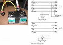
) but it sounds pretty good in comparison to my old amp. Now to buy some replacement tubes as I am curious as to the difference they can make. Was a bit bit of a whim purchase from ebay so keen to have a tinker.Hi 4a42, welcome to the Yaqin club, well my MC10L is nearly 3 years old now and so far no problems. I have attached a couple of photos of the jig I use for looking at the bias. The 270 Ohm resistors are most important as otherwise the extra wiring can make the output stage unstable. They are called grid stoppers and should be placed close to the valve base grid1 connection. You can calibrate the meters, both at the same time, using an external controlled Lab DC supply connected through both circuits. I adjusted the shunts slightly so that 35mA hits the same place on the meter scales. Of course you could use a battery operated panel meter switched across two precision resistors but the Maplin meters are cheap.
I added the two 2mm sockets later for checking the heater voltage just to make sure the mains transformer was being run with the right input. On my Yaqin I had thought it was a 220V model and I ran it from an auto transformer. However the test points showed only 5.5V so I ran the amp straight off the 230V mains and the heaters are now correct. It does pay however just to check you have a 230V model and not the 220V one.
The Octal plugs I made from some old valves after carefully removing the glass envelope. If you do this, make sure that there is a pin in all 8 positions, sometimes valves have a missing pin.
I find this little gadget most useful repairing guitar amps and the last Marshal Amp that came my way had valve currents all over the place. However, by noting the currents drawn by each, I was able to mix 'n' match the 4 valves so that the currents through the output transformer were equal. The guitarists reckons the amp sounds better than it ever did and it is still going strong after many hours of hard gigging.
Attachments
- Home
- Amplifiers
- Tubes / Valves
- Yaqin mc10L