Thanks Les, Looks like I have recieved the wrong schematic and yours is definately the correct one,did you get the photos I sent to you? the board layouts appear nearly identical as far as i can see from the 2 sets of photos, will run the amp for a week or two now and then decide on tweaking, the mains transformer seems to be running a lot cooler now with very little hum, and since biasing sounds excellent, Thanks again, Brian.
OK Brian, yes I received the photo's alright and they sure are very similar. The original schematic was very useful as a starting point for re-draw, mine are still not 100% but almost. I fitted the 220nF 630V Audio grade coupling caps today and they certainly improved the bass and lower mid range, not a lot but noticeable. I also fitted the voltage equalisers across the main smoothing caps while I had the pre-amp board out. I intend to order the parts from Maplin soon to fit the mains spike suppressor in place. Maplin's do all the components :-
1 OFF, VDR MAPLIN HW13P
2 OFF, X CLASS 0.047 CAPS MAPLIN N68CN
Not too pricey either so worth doing I think.
Yes it is a nice amp when everything is set up right, it has it's design of manufacture flaws in places but for the money, who can really complain. Enjoy! Les
BTW I did visit that site with pics of the burnt MC10K, a different amplifier but does appear to have a problem with reliability. I cannot put any of my views on this until I get one that I can investigate as I am sure there has to be another reason like for example incorrectly set standing bias, but John did a great job of repair.
gasman said:Thanks Les, Will be visiting John as he only lives a couple of miles from me, What thoughts have you on the 680 uf caps on my amp, 680 uf, as opposed to the 470 uf fitted to your MC10L, cheers Brian.
That's very interesting Brian and something I failed to notice. I did notice however that the original value of the capacitors was 330uF, so Yaqin went from that to 470uF and then to 680uF. I do not have any issues with the present 470uF on my amp and I would have thought that even the lower values of 330uF would be fine for a valve amplifier.
Your amplifier also sports proper test points for the bias adjustment, it's a pity Yaqin did not silk screen the factory bias settings onto the PCB. I wonder what other changes we can find. When I fit the new 6CA7's I am going to try to set up the output stages slightly different.
First set the standing current, probably 30mA, then slightly adjust one of the pots for minimum 100Hz on the scope. This wil give equal but opposite currents in the output transformer. I also want to be able to adjust the phase splitter for minimum overshoot on a square wave input (minimum harmonic distortion) but yet to decide which is the best resistor to adjust to achieve this, the 51k looks a possibility.
Les
It will be interesting to find how the 6CA7,s sound when you have set them up Les, I,ve heard good things about them as replacements for the EL34,s, incidently slightly off topic I know, I am thinking of changing the Burr Brown 2604 op amps in my MHZS CD66 tube output cd player, have you got any ideas on what might be a worthwile upgrade, cheers,Brian.
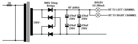
Can't help you with the DACs Brian, not enough experience here but a good surf around may bring up something. I am pleased with the 6CA7's and my many visitors think they sound great. I keep looking at the power supply of the Yaqin and can't help thinking something should be changed here. I am posting up the HT part on the Forum and hoping someone can add advice or support some of the concerns I have, maybe I am worrying too much. well I have added some voltage equalizers across the caps for starters and just wondering if it is worth adding some 6V 200mA wire ended pea bulbs to protect the transformers if any of the output valves went down. I would like to hear from anyone who may have tried these. Yep, I could use a fuse, I know, but a small pea bulb would be easier to fit in the amp and take up minimal space. The switch-on surge taken by the bridge rectifier must be a bit harsh, I just hope it can take it. It must be even greater in your version with 680uF! Also, should I be concerned about the 800V piv rating of this rectifier? It's just that my experience keeps telling me the margins are a bit too close for comfort, just hope the rectifier manufacturers are providing a good safety margin.
Still it's nearly 18 months old now and no smoke yet from the HT circuits! Cheers, Les
Still it's nearly 18 months old now and no smoke yet from the HT circuits! Cheers, Les
Attachments
Glad to hear its sounding nice with the new valves Les, Yes the power supply does concern me sometimes, I havent had any problems with the initial surge on switch on since I changed to the 2.5 amp time delay fuse, it would be interesting to see if anyone else has come up with a solution to address this, have run the amp for 12 hrs the other day, admittedly the mains transformer got a bit on the warm side, I think a bit of extra ventilation may help there as it doesnt seem to get quite as warm when the lid is off, My next door neighbour works in a sheet metal fabrication shop, might pick his brain to see if something can be done with the green top hat cover. Also I rechecked the bias when I had the lid off the other day, V4 had crept up from 300mv to 326mv, must be a little bit of drift at the pot, will keep an eye on it, I usually leave it an hour after adjustment before I take my final reading, will check it once a month to be on the safe side,I have bought a set Svetlana 6n1p,s to try, will have them Weds the specs look the same as the chinese 6n1,s so I,ll assume they are a drop in replacement, I,ll let you know how they sound, thanks for the drawing,Brian.
I think you will notice quite a difference with the svetlana's Brian.
I often wonder if it is possible to chrome plate the pots, perhaps you could inquire. Might be possible to drill holes or slots on the rear part so that they are not visible from the front, just a small amount of ventilation would be of great benefit I am sure. The down side to fitting 6CA7's is the fact you have to unplug all 4 before you can remove the top plate so I scratched marked them I II III IIII on the hidden side so I get them back in the right sockets LOL!
Les
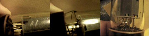
By the way Brian and anyone else viewing this post, watch out for a defect in any EL34's you buy. One major reason for trying the 6CA7's was the fact that I discovered to my horror that one of my Harma Cryogenic EL34's was not assembled correctly. I have been using it for months and it could have cracked, admitted air and probably done a lot of damage to my amp, just glad I spotted it in time. The attached photos show how the electrode to glass spacers should be, the second photo shows how one spacer was not in position. This made quite a large dimple in the thin glass tube, unfortunately my camera does not focus too well at short distance and the actual dimple size does not appear that big. But it is! The stress at high temperature at that small spot! Wow a lucky escape I think, check your spacers!
Cheers, Les
oops, photos not come up, will try again
Cheers, Les
oops, photos not come up, will try again
Attachments
Had the Svetlana 6n1p,s in for 5 days now and they will definately
be staying in, not that the stock 6n1,s were bad but the sound has improved with a smoother top end more controlled bass and midrange, I suppose to sum it up the sound is more fluid and easier to follow, Les, I inquired about chrome plating and it really wouldnt be cost effective unless a large batch was sent, I will let you know how I get on with the ventilation, I have decided to drill a few holes at the rear of the pot out of sight and tidy the job up with some grommets should be ok if I take my time and drill pilot holes, Cheers Brian. B.T.W checked the spacers in my EL34,s all ok.
be staying in, not that the stock 6n1,s were bad but the sound has improved with a smoother top end more controlled bass and midrange, I suppose to sum it up the sound is more fluid and easier to follow, Les, I inquired about chrome plating and it really wouldnt be cost effective unless a large batch was sent, I will let you know how I get on with the ventilation, I have decided to drill a few holes at the rear of the pot out of sight and tidy the job up with some grommets should be ok if I take my time and drill pilot holes, Cheers Brian. B.T.W checked the spacers in my EL34,s all ok.
Hi Brian, Glad you found the change of 6N1's so effective, as I did.
I would never have believed the resultant change in general tone if I had not experienced it myself. Thanks for the info on the chrome plate and the adding of ventilation holes. My mains transformer pot gets quite warm after a long session. Just wondering if vents near the top would suffice and rely on convected cooler air coming up from beneath, typical chimney effect. Let us know if the pot is keeping much cooler.
Les
gasman said:...using an MZHS valve output cd player, sounds just slightly lively at the top end at the moment but its early days yet
Can you keep us up-to-date about this CD Player? I was considering this player taking for granted the output tubes would give a warm natural sound.
Cheers
fauxpas said:
Can you keep us up-to-date about this CD Player? I was considering this player taking for granted the output tubes would give a warm natural sound.
Cheers
HI, yes i,ve had this player for about 14 months now , came with chinese 12ax7,s which I upgraded to seimens ecc 83,s which beefed up the bass and made the top end more fluid and slightly smoother, I wouldnt say there was a warm sound to this player but the sound to my ears is open and an honest reproduction of the source material, However I did find extra warmth with some tungsram ecc 83,s installed, I really liked these tubes but one went down so I will be searching for a replacement, Overall its a very good player, beats a lot of so called high end units I have owned and you can roll the tubes to your hearts content, I am trying a few different op amps at the moment. Cheers Brian.
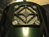
Actually got round to fitting the fan grille to the hidden side of the mains transformer can. Surprisingly the can top gets even hotter than before which I put down to the chimney effect drawing more heat away from the transformer so has to be a good sign. Just wondering now if it is worth putting another grille at the base of the can to increase ambient air input.
Les
Les
Attachments
Hi-Q said:Actually got round to fitting the fan grille to the hidden side of the mains transformer can. Surprisingly the can top gets even hotter than before which I put down to the chimney effect drawing more heat away from the transformer so has to be a good sign. Just wondering now if it is worth putting another grille at the base of the can to increase ambient air input.
Les
Hi Les, Hope you had a nice xmas and new year, might be an idea to take the xmesh out of your ventilation grille and pack the feet up underneath the base of the amp by 15mm or so to simulate more airflow and see where that takes you before drilling the pot again, also the ventilation slots in the base below the mains transformer are quite narrow, maybe something could be done with those, Cheers for now ,Brian.
- Home
- Amplifiers
- Tubes / Valves
- Yaqin mc10L