The biggest issue replacing these caps, is space.
I used Mundorf Silver & Oils, then after a re-build moved to Alaxandra caps that would never have fitted otherwise.
ClarityCaps ESA seems like a good choice, and they should fit no worries, go with the 630v.
Thanx Data, can you confirm before I place the order that I need:
x4 (0.1uF) and
x2 (0.22uF) ?
I put Wimas in place of the blue caps - it was a major PITA to do. The Yaqin MC-10T is probably the most difficult to work on amp I have ever owned.
Try a Sonic T-amp......

Clarity Cap ESA 0.1uf/630v measure 27mm x 20mm, so will fit fine, keep the orientation of the caps so that the signal travels in the same direction as the print on the cap/s.
Don't worry about the other two .22uf caps.
Ok thanks, guess the ones I will be removing will have directional writing for me to follow the direction
You will be able to see the way they need to go by looking at the circuit before and after each cap.
Ahhh really lol. I am self confessed blind to this then, unless there are directional arrows or something ?
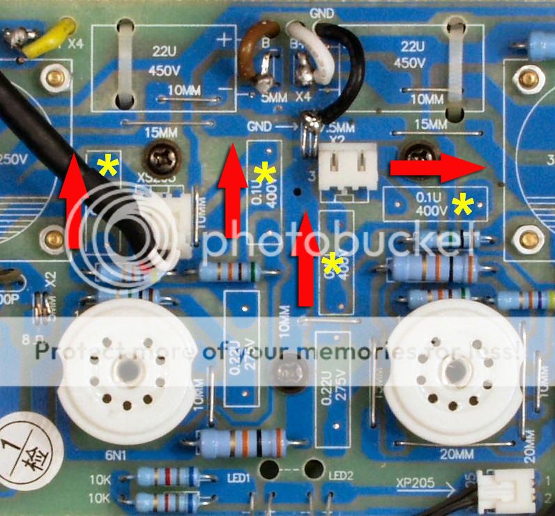
These are the connecting leads from the pre amp PCB to the power PCB, just follow the PCB traces from the caps to these as they leave the pre amp PCB.
That should show you the direction they need to be.
That should show you the direction they need to be.
Attachments
Last edited:
You will be able to see the way they need to go by looking at the circuit before and after each cap.
Each output end will lead to the interconnecting wires from the pre amp PCB to the power PCB.
Thanks that's useful to know, will make sure the writing on the caps ends in the direction of those wire connectors. Many thanks
Barbie, Isn't that one on the right the other way round?
Or am I looking at the traces wrong....
Yes and I was just about to mention this to you, wow, I would have put that one the wrong way.....
I'm not sure how much worse it would sound if you did get them around the wrong way, It's just that they are said to sound better with the foil end of the cap at the output, this is normally indicated by the direction of the writing, in the end that the writing starts, and out the foil end where the writing ends.
As I understand it anyway, unless i have it *** about.
As I understand it anyway, unless i have it *** about.
Sorry, you would need to refer to the makers literature for the board/build, as I can't see anything in that pic.
I can't identify any positions where caps are needed?
Apart from the two electrolytic caps, they all look like surface mount caps, indicated with the "C" prefix on the PCB like all those near the output.
I can't identify any positions where caps are needed?
Apart from the two electrolytic caps, they all look like surface mount caps, indicated with the "C" prefix on the PCB like all those near the output.
Last edited:
About to order the caps when I realised I've got a tiny little D class amp not used in years in need of caps - it hasn't got any ! Any idea what value I should get please, then I may as well order all at the same time
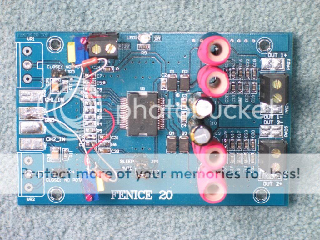
You would put the capacitor right where your DC supply voltage comes in (screw terminals at the upper left in this picture I think). There appears to be only one voltage for this circuit so you'd need only one cap. Try a 0.1UF at 2X your rated supply voltage (typically 18V for these D amps).
- Home
- Amplifiers
- Tubes / Valves
- Yaqin mc10L