Well I did it! This morning, with a feeling of hope in my heart, I pulled apart the PSU of my Aikido. Actually, I didn't need to do too much. I removed the 125-0-125 trafo, omron relay, diode bridge and snubber network. In place, I added a 275-0-275.
Once the universal primaries had been set for 120VAC, I was going good. The octal socket for the Amperex delay tube was re-wired for a tube rectifier, and it was ready to fire up.
Being cautious, I pulled the B+ and PSU GND from the Broskie PCB, plugged in and measured 370VDC on the PSU output - Phew! Then I re-wired the PCB, added my cheap Russian nasties and fired-up the Aikido again. It was great to watch the voltage rise to around 370VDC, then after around 15 seconds (my guess as the 6SN7s warmed-up), the B+ dropped to around 312VDC - PHEW and more PHEW!
Initial playing with my good Sylvania and RCA in place of the nasties revealed a couple of things:
1. My low level, undescernable hum was replaced with a very, very quiet but clearly 120Hz hum. My ear really needs to be close to the speaker to hear it.
2. The buzzing B+ trafo has stopped!
3. The music sounded much improved over the diode bridge. How different? Well, it is hard to say, but it seemed smoother and warmer, and Kara reckoned that it sounded much clearer.
It's early days and the new PSU components need to settle, but I love it!
As for the hum, well I can live with it, as it is very difficult to hear. BUT, being 120Hz, I feel comfortable about it being the result of poor filtering. My tubes pull around 24mA which for a B+ of 312 and chokes of 10H, in a LC filter means that I am not pulling enough current to allow the chokes to function properly. It could be that, but I am using a 0.68uF "tuning" cap so maybe the PSU is more like a CL filter. I can replace the 0.68uF with a 1uF or 1.5uF, which will bring the PSU into much clearer CL filter. I could also add a current sink across my final cap to pull a little more current, maybe up to 34mA.
Anyway, I feel pleased at knowing that easy "tweaks" will likely bring the PSU to a state in which hum is a thing of the past.
Charlie
I doubt if your 0.68uF tuning cap will change the electrical characteristics to a noticeable degree. You could try a bleeder, as you say, to increase the choke current.
Since you have 120Hz ripple, it should be possible to reduce it simply by adding more filtering. Increasing the capacitor after the choke is the first obious thing to try but, if that's the final stage in the filter, you should make sure it's a good quality cap.
The ultimate answer would be a regulator = no hum.
Ray-moth and Jayme,
I could go with regulation using tube rectifiers, I think I would need three of them.
For my caps, I am using:
0.68uF - "tuning" cap
60uF motor cap
60uF motor cap
Yes....I could use a larger value for the final cap as it is always better to have the final cap slightly larger than the others.
The bleeder resistors should make a difference. The trafo is only 50mA DC rated, so I want to be very sure about not exceeding that value.
Are you aware of Broskie's tables for tube and resistor selection? If you are, then for example if I read for a 6SN7 300V at B+ and a cathode resistor of 680R, then does his column labelled lk refer to current drawn by the tube? If it does, does it mean each section or the entire tube?
I have always taken it to refer to current drawn by the entire tube. In which case, my Aikido draws around 7.2mA for each output tube and 4.5mA for each input tube. This gives a total of 23.4mA.
If I am reading the table correctly, I can add sufficient bleeding to bring current draw up to around 34mA. Alternatively, I could use current-drop with and without tubes to estimate current draw for the entire circuit, then add a little for draw across my safety resistors on the caps.
Charlie
Are you aware of Broskie's tables for tube and resistor selection? If you are, then for example if I read for a 6SN7 300V at B+ and a cathode resistor of 680R, then does his column labelled lk refer to current drawn by the tube? If it does, does it mean each section or the entire tube?
Charlie,
as I read the aforementioned table the current draw of the tubes depends on B+ and the value of the cathode resistor. With a recommended value of 470R for the first stage the tube draws 7.2mA EACH half as listed in the table. With rk = 240R for the output stage the tube draws 10mA (each side) for a grandtotal of 34.4mA. I assumed that you are using 6SN7 in both positions.
Plugging that into PSUDII and assuming/vaguely remembering that you are using two 10H chokes I am nowhere near 300V at the psu output with a .68uF first cap. But it is easy to play with this value to arrive at the desired voltage. But then, I am just guesstimating your actual psu...
...using tube rectifiers, I think I would need three of them.
You won't need three rectifiers for a regulated psu, just build a psu that goes like: trans-rectifier-filter section-regulator. But your current psu has the potential to be quiet, I think.
Hope this helps just a little...
Stixx,
I always assumed that Broskie's table listed values for the entire tube (as far as lK was concerned). Thus for a stereo board I estimated:
B+ 300V with 470R and 1000R for rK, I would get 4.5mA x 2 for the 470R tubes and 7.2mA x 2 for the 1000R tubes totalling 23.4mA.
By your reckoning, I should be doubling this number because the lk's listed by Broskie are per side of tube not the whole tube. This would mean that the actual tube current draw would be more like 46.8mA.
Given that I am unsure of this, how would I measure it, or use tube datasheets to get an idea of the total current drawn by four tubes. Sy did once try to explain it, but it seemed like something was missing. The 300V gets halved so that each side of the tube sees more like 150V for a B+ of 300V.
My new PSU consists of: 550VAC; 5V4GA; 0.68uF; 10H; 60uf; 10H; 60uF. When I model this in PSUDII for 23mA, I get a voltage of 317VDC. If I model it for 46mA, I get more like 260VDC. In reality, I see something like 311VDC on the output.
If you have any firther enlightenment, please let me know.
Charlie
Charlie,
sorry for bringing more confusion, but as for the current draw YOU are right...
I checked my own values (I am in the process of building an aikido headamp with 6CG7 and 6H30), and current draw as listed is per TUBE, so your calculations are correct. You flipped the numbers, but total current draw should be around 23.4mA.
As far as I know (being quite a novice myself) you can calculate the current draw using Ohm's law ( I= V/R). Measure the voltage across the cathode resistor and put it into the equation. Example: cathode resistor 470R, measured voltage 3,5V at the bottom Rk, I=7,4mA.
(Hope nobody's beating on me now...") )
)
You're almost dead on...311 to 317V is a deviation of 2%!!
I'd call that perfect...
Good luck with your modding,
Oliver
sorry for bringing more confusion, but as for the current draw YOU are right...
I checked my own values (I am in the process of building an aikido headamp with 6CG7 and 6H30), and current draw as listed is per TUBE, so your calculations are correct. You flipped the numbers, but total current draw should be around 23.4mA.
As far as I know (being quite a novice myself) you can calculate the current draw using Ohm's law ( I= V/R). Measure the voltage across the cathode resistor and put it into the equation. Example: cathode resistor 470R, measured voltage 3,5V at the bottom Rk, I=7,4mA.
(Hope nobody's beating on me now...
)My new PSU consists of: 550VAC; 5V4GA; 0.68uF; 10H; 60uf; 10H; 60uF. When I model this in PSUDII for 23mA, I get a voltage of 317VDC. If I model it for 46mA, I get more like 260VDC. In reality, I see something like 311VDC on the output.
You're almost dead on...311 to 317V is a deviation of 2%!!
I'd call that perfect...
Good luck with your modding,
Oliver
I am glad that was cleared-up. I tried Ohms Law, but plugged in 300V, then 150V. Where did you get 3.5V. I suppose I must go back to the schematic and see what lies between B+ and the plate to figure this out.
Anyway, the upshot of the current-draw is that 24mA with 312V means that my chokes don't have enough henries to properly filter out ripple. Prior to going tube-rectified, I had an extra current draw of around 20mA using a resistor across the final cap. I may simply reinstall this. The B+ will then drop, which I may be able to bring back up using a 1.5uF cap instead of the 0.68uF. I sense a degree of synergism here!
Thanks for your input. You'll not get any beating whatsoever from me - look at the ridiculous number of posts I make to this group and you'll see that my blundering gives me no reason to complain at all!
Regards,
Charlie
Where did you get 3.5V.
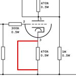
The voltage across the cathode resistors is actually that low, it sets the bias. The mentioned 3,5V were just an example, but it should be in the neighbourhood...
Put the probes of your DMV across the bottom cathode resistor (see image) and note the voltage you read. It should be somewhere between 2 and 4V ....put this into the equation...et voila!
Anyway, the upshot of the current-draw is that 24mA with 312V means that my chokes don't have enough henries to properly filter out ripple.
I wouldn't worry too much about the chokes. I am using chokes in both of my current headphone amplifiers (C3G and a Morgan-Jones variation), both are drawing between 23 and 32mA only, but hum is "almost" indiscernable....over headphones!
Try the bleeder resistor across the final cap, do not worry about voltage too much at this point and listen whether there is an improvement. When there is still hum, I'd put in more capacitance as someone already suggested. It's the cheapest and easiest way instead of pulling your chokes....just try a "lowly" electrolytic cap in the last position with your motor cap.
I know how bothersome hum can be from my own experience...it took me months to get my C3G headamp hum-free, but it was a good learning experience being my first tube project. In my case it was improper wiring and grounding, but my endless fiddling and trying to improve helped in the end...now it sounds truly glorious and is deadquiet!
regards,
Oliver
Attachments
Oliver,
OK, I'll make the measurement. I think it may be 4.5V for 300V B+ which is what Broskie uses in his original schematic. I expect that with 312V, I'll not notice any appreciable deviation, but you never know.
I have modelled my PSU with differing degrees of capacitance. If I use 107uF on the final (the 60uF, plus 47uF electrolytic), and add another 22uF to the first 60uF cap, I get really low levels of ripple 0.6mV or thereabouts.
What are the negative aspects (if any) of adding extra capacitance? Is there a maximum amount?
When I get chance, I'll drive out to my local surplus place and see what motor-run caps they have. I am sure I can find a 100uF there and that it'll cost less than buying a new electrolytic.
Regards,
Charlie
- Status
- This old topic is closed. If you want to reopen this topic, contact a moderator using the "Report Post" button.
- Home
- Amplifiers
- Tubes / Valves
- From diode to tube rectification in my Aikido