I have a set of back loaded horns w/ FE208E Sigma drivers. My first tube amp was a Fountek Altitude 3500 which was PP w/ EL34's. I am now using my SimpleSE with KT88's. It sounds great but seems to be a little bloaty with the bass. I don't like the excursion I am seeing on my drivers. I have switches installed for CFB/No CFB and UL/Triode. I like the sound most with Triode mode and no CFB. Does anyone have any recommendations on how I can correct this? Would a tube swap be in order? I have EL34's and I believe there are a number of other tubes that are "plug and play" with this amp.
It sounds great but seems to be a little bloaty with the bass.
Such is the nature of SE amps, and if you want to follow that path - get used to it. I personally can't as I like to listen to electric music and theres a lot of stuff going on in the deep bass region that I need to hear.
I have heard it said that a solution to this problem is to regulate your +B. This will tend to keep the current to the speakers more constant, and hence will help to control your driver on both the push and pull of the cone.
Shoog
awhite1159 said:I am now using my SimpleSE with KT88's. It sounds great but seems to be a little bloaty with the bass. I don't like the excursion I am seeing on my drivers. I have switches installed for CFB/No CFB and UL/Triode. I like the sound most with Triode mode and no CFB. Does anyone have any recommendations on how I can correct this? Would a tube swap be in order? I have EL34's and I believe there are a number of other tubes that are "plug and play" with this amp.
Sounds like underdamped woofers. You can improve the damping by lowering the Zo with gNFB. Running without gNFB leaves you strictly at the mercy of the components you use. Other than a VT with a smaller r(p) there isn't much you can do about it.
do you listen to any minimal techno? here's a great mix by Franco Bianco I've found...Shoog said:I personally can't as I like to listen to electric music and theres a lot of stuff going on in the deep bass region that I need to hear.
http://www.pinksilver.net/podcast/media/Franco_Bianco_-_Bahia_Chica_-_2007_-_320kbps.mp3
Thanks very much for the replies.
I have listened to rock all my life but have recently started listening to more jazz of the fusion and acid type. Examples of what I am listening to are Oz Noy, David Fiuczynski, Ostric tentacles, etc. I should clarify that the bass is very 'tight' as would be expected from horn bass. It just seems that when I get the spl above 100db, I see alot of excursion and although I don't have any audible IM distortion, I can't imagine it is not there. Perhaps this characteristic is normal? The NFB seems to help but I hear a slight decrease in the higher frequencies as a result. I think this SimpleSE amp is a very good amp but it was a beginner amp and now that I am certain I like the sound of a tube amp better, I would like to move on to building a really good amp. I know I don't need alot of power so would the Paramour SET from Bottlehead be a good choice?
I have listened to rock all my life but have recently started listening to more jazz of the fusion and acid type. Examples of what I am listening to are Oz Noy, David Fiuczynski, Ostric tentacles, etc. I should clarify that the bass is very 'tight' as would be expected from horn bass. It just seems that when I get the spl above 100db, I see alot of excursion and although I don't have any audible IM distortion, I can't imagine it is not there. Perhaps this characteristic is normal? The NFB seems to help but I hear a slight decrease in the higher frequencies as a result. I think this SimpleSE amp is a very good amp but it was a beginner amp and now that I am certain I like the sound of a tube amp better, I would like to move on to building a really good amp. I know I don't need alot of power so would the Paramour SET from Bottlehead be a good choice?
I would say that the things you are experiencing with your SE amp, you will probably experience with most SE amps unless you go for a very low impedance output valve.
Before splashing any more money, take a look at the RH807 and RH84 designs. These employs a different kind of feedback which is simple to implement and can dramatically improve the bottom end without killing the overall sound. I would advise trying it with a 100K resistor before doing anything else.
Then I would advise you broaden your horizons and consider some of the top flight PP tube amps. Look at Gary Pimms Tabor amp (if you can find it). Also consider the Amnity or Raven amps. There is also a Magnaquest 2A3 amp which uses a centre tap choke as a phase splitter. Then there is the Vacuum State 300dba.
IMHO I believe any one of these amps can do everything that a SE amp can do, but considerably better. Remember that sloppy bass is almost a universal reservation about SE designs.
Shoog
Bruce Rozenblit is often referring to this problem and states that it is a result of the efforts of avoiding FB. No or low FB increases Zout and lowers damping factor resulting in no control of the speaker cone.
This "phenomen" is often said to prove that tube amps can deliver deep bass, but is a quality flaw.
Get the two books (one i printed form and the other in PDF) from Transcendent Sound
This "phenomen" is often said to prove that tube amps can deliver deep bass, but is a quality flaw.
Get the two books (one i printed form and the other in PDF) from Transcendent Sound
You all gave possible causes.
May I add that, in an SE amp, the primary inductance of the OPT is usually lower than in a PP (the consequence of the unavoidable gap combined with a too small iron).
This causes heavy current peaks at lowest frequencies (specially if the power tube has a lo Rp) wich may produce B+ sag (as stated by Shoog in post #3).
This disturbs the driver and produce an effect near to "damped motor boating".
In this situation NFB makes things even worst !
Regulating the supply of driver stages alone may help.
Reducing link cap in the grid of the power tube sometimes proves satisfactory.
No need to deseperatly "push" basses in an OPT who will short'em producing desatrous side effects
Yves.
Thanks to all. I kind of new at this and I appreciate the feedback. Soundbrigade, thanks for the book recommendation. I will take a look.
Salas, I understand what you are saying but I am concerned about adding damping material. They are back-loaded horns. However, just like most 'horns' for domestic use they are a hybrid of TL action and horn action. The horn action kicks in around 55Hz but anything below that down to about 35Hz, I rely on TL action. Adding any more damping material would have an effect on the tuning and the sensitivity. Taking your advice though, I'm wondering if a change to the throat size or coupling chamber might help.
Salas, I understand what you are saying but I am concerned about adding damping material. They are back-loaded horns. However, just like most 'horns' for domestic use they are a hybrid of TL action and horn action. The horn action kicks in around 55Hz but anything below that down to about 35Hz, I rely on TL action. Adding any more damping material would have an effect on the tuning and the sensitivity. Taking your advice though, I'm wondering if a change to the throat size or coupling chamber might help.
A back horn-loaded driver becomes completely unloaded below the cutoff of the horn (or TL) so huge cone excursion will result from any subsonics coming either from the music or from the own amplifier due to the usual lack of regulation against supply fluctuations of the working point in most tube designs.
Also, the impedance figure of a small back loaded horn/TL system usually contains several peaks in the bass region which makes it quite hard to drive for any (tube) amplifier having high output impedance.
To find out whether the problem actually comes from the tube amp or not, you could borrow a standard solid state amp with NFB (which will be free from low frequency artifacts) and try it with your speakers and the same music...
BTW: If you damp those impedance peaks you will lose all the efficiency of the horn/TL. The only way to get flat impedance from a horn is to make it absolutely huge. If you don't know what you are doing, it's better not to modify horn/TL stuffing.
Well, I designed the horns but that still doesn't mean I know what I'm doing.
The Fc is 35Hz. I used to have an Adcom GFA5802 and it didn't sound as good but it certainly controlled the excursion better.
I agree with not adding any additional damping material. I wish I didn't have to put any but it was necessary because the horn is compromised and it helped to even out the peaks in the response at lower frequencies.
I agree Eva. The problem occurs when I play music that I know has bass below the Fc of the horn and below the 1/4 wave freq. of the TL.
Shoog, I did notice the excursion problem was not as bad with my Fountek Altitude 3500 which is push-pull. So I will take your advice and look at the amps you mention.
So, to get back on subject, I guess I have alot of reading and research ahead of me before building my next amp.
I just caught this thread (major project at work). First let me address a few of the previous suggestions. Regulating the driver power supply will have no effect on this amp, the driver is fed by a CCS. Regulating the main power supply may provide some improvement, and it may not.
All of my amplifiers are initially developed using regulated supplies, then a power supply is developed that comes as close to the regulated supply within budget. It has been my experience that the on board power supply augmented with a large (80 to 100uF) motor run cap works almost as good as a regulated supply.
You mentioned trying different output tubes. I find that I get the best bass from the KT88's. The Output Transformers make the biggest difference in generating big bass. Which ones are you using?
I get solid wall shaking bass from the big Hammond transformers, but somewhat loose flabby bass from the small Edcors. On the other hand the Edcors have the best highs, and the Hammonds sound like you put a blanket over the speaker.
George,
Thanks for the reply. I am using the KT88's and the bass is exceptional. I have a tendency to put things loud and I can say that I was probably pushing 103db+ when I observed the excursion problem. I have the Big Hammond's. If I remember correctly they are either the 1625's or 1628's. I get wonderful hi frequency response (No blanket) especially in triode mode w/ no CFB. So either I blew my ears out when I was younger or it's the Fostex FE208E Sigma's and the T90A's.
Just so you know, I think this amp is a great amp. I'm just itching to build another one that is more of a challenge.
Andy
I'm just itching to build another one that is more of a challenge.
Andy [/B]
In a nutshell , here we go...take all this in your next one...
This one of the most common and misunderstood design flaws from tube amp design using global nfb. Push pull amps are notorious from over-design in the LF end, from a quality point of view and also from high power levels. The culprit is too high value interstage caps esp in split load and other designs with a wide b/w output transformers i.e capable of Hz response. Essentially the amp open loop gain at LF end has to „let off“ by a determined amount to avoid subsonic LF & HF oscillation, and effective feedback reduced at the frequency extremes. A simple bench test is to increase global nfb til amp motorboating is detected with osc'scope and also HF instability /oscillations may be included. Most often it is the LF motorboating that will come first.
The Radiotron handbook doesn’t mention this in detail but a well designed 3 or 4 stage amp will show signs of instability when global nfb total value is pushed around 36dB. (i.e nom 20dB should accept an extra 16dB). That is mathematically explained in the 4th edit.
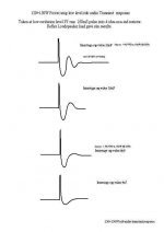
Far more informative to get correct interstage capacitor values with a standard amp circuit designed nfb, say 20dB is to use a single pulse square wave transient generator with long mark-to-space ratio. The amp in this example has a o/p transformer design cutoff at 25Hz rated at 100W. Amp is set up with dummy load and a low level signal (ref ground without input cap, so near DC behaviour can be observed) applied direct to 1st stage input i.e eq to 3W o/p is used to avoid overloading the output transformer at LF. A time base 2-5 secs is selected with.waveform on a long persistence oscilloscope. Those skilled with smps design will know exactly how important this is except at far higher frequency.
A diagram of tube amplifier LF transients is shown. Comments on the uppermost overshoot is it gives lowest LF thd but considerable overhang on bass transients creating a muddly sound. Designers shouldn’t build amps for lowest thd at lowest frequency but instead examine transient performance at a very low level sub-cut off response. The optimised amplifier will have an excellent and well damped loop controlled bass transient response required by digital signals and not so effected by loudspeaker performance.. In many older designed amps, the interstage cap values from 1st stage to driver stage were selected arbitary values and nearly all the designs examined, the cap values can be reduced by nearly half, improving performance.
Damping factor has been mentioned by others, but it is the amplifier that must be in control, NOT the loudspeaker and a well designed amplifier loop response will provide exceptional results and will flatten peaks and troughs in the LS response.
To us who meddle with output transformers and physics, the near optimal Q waveform findings are coincidental to match with roughly 1.4 % iron harmonic (2nd) thd at the designed cut off frequency of that particular o/p transformer. Remarkable, because that is that thd figure quoted for specific core excitation that matches Bmax, turns and other parameters at the lowest frequency and power of operation.
The best example of an obsolete commercial amp with these considerations is the original GEC 88-50 Woodville/Heath 1953. So many people commented the low end of that amp has excellent power handling, and low intermodulation thd. Thus from the method described it should be easily able to match a particular output transformer for an amplifier, rather than experimenting with wild values.
So those who use closed-BH loop toroid o/p transformers in tube amp designs have to pay exceptional attention to open loop values v.s thd to avoid overhang. E & I definitely has a destinct advantage simplicity.
Good luck !
richj
Attachments
salas said:Will this be satisfactory to run the nice test you suggested?
So long there is no input cap nor input transformer and the volts low. As mentioned mark-space-ratio must be quite long. (square wave short on- long off time at least 1:3).
This reminds me of LS motional feedback system analysis which included the LS characteristics and box, but in our case we start with an imperfect tube amp.
One should immediately see that a well designed DC transistor stage amp with perhaps 200dB feedback represents the most perfect power source, but again these aren't immume from HF problems especially when a drastic phase change occurs i.e a series L&C are placed across the output terminals.
For those not graphically inclined, I am essentially re-examining the highschool Bode and Nyquist plots which detail stability margins, which are often quite large. Often within a design there is considerable scope within the stability margins for proper optimisation..
The 100W amp which I did my experiments on also had a step response global nfb loop set at 20dB, and could be increased to 36dB when instabilty on both HF and LF was noticed with dummy load. I would also mention that after going through the complete stabilty and transient examination I found the sonical differences between tubes was more difficult to assess. This is only my opin but may hold some truth.
Remember, alot of old tube amp circuits were designed with an single cone full range LS, Tannoy etc and now the phase picture has changed with passive component cross-overs thrown in. Tough time for some.
There is another problem; the response of many tube amps rises below the output transformer cutoff..a strong signal can overload the tubes as o/p transformer mag flux Bmax rises to Bsat...various remedies... as another theme.
DSP is far easier!
richj
richj
Thank you richwalters for a very interesting explanation!
I have peen puzzled by some old amps with rather small coupling caps. I just did not understand that LF frequency limiting caps within the feedback loop could make sense, so i replaced them with "better" ones. I now see that the old designers may have understood something that I did not
I am not sure however how the philosophy can be applied to the Simple SE, being a circuit without global feedback.
To understand the curves, I figure the rough order of magnitude as follows:
Pulse-width is 250 ms, and x-axis is around 2-3 seconds. The damped resonance will thus be below 1 Hz (motorboating territory). The 5-10nF coupling will in a typical amp give a -3dB point around 50-100 Hz (not considering FB), and -20dB in the 5-10Hz range. I am Confused.
SveinB.
- Status
- This old topic is closed. If you want to reopen this topic, contact a moderator using the "Report Post" button.
- Home
- Amplifiers
- Tubes / Valves
- Question about "bloaty" bass with SET and KT88's