OK..settled on components & I'm doing the layout (Paper layout), my question is about the Heater proximity to the 5691 tube, I have it fairly close. Are there rules of thumb on transformer to tube spacing? Refering to the layout attached, I can move one of the heater transformers but not both under the capacitor stack next to the mains TX. Note: the diagram is not to scale and it is tighter spaced as shown.
I plan on using alot of grounded sheathing for signal and heater wiring...is that a good idea or does it bring up further unwanted effects?
I plan to run HT and ground bus parallel to the switch shaft and I will make the shaft of plastic to avoid the shaft acting as a RF director/reflector (Think Yagi-Uda).
_____________________________________Rick...........
Attachments
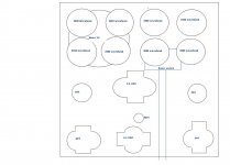
No rule of thumb except basically not to do it. The driver tube is the most sensitive point in the entire amplifier and should not be near the power transformers, filament or otherwise. Place all of the power transformers as far away from the input circuitry as possible. OPT's should be placed with regard to hum pick up as well.
Also I don't really understand why you need enough capacitance to run Manhattan for a couple of seconds? Unless you are running dc filaments there is no need for so much capacitance in a tube amplifier. No more than a couple of hundred uF are required, particularly if you use a CLC type.
Resist the urge to build on too small a chassis, it limits placement flexibility and in 0 fdbk designs may prevent a hum free implementation.
Kevin:
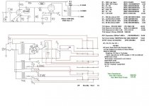
You've probably seen my design, its' an adaptation of the "Simple 45"......with SS rectification without a choke.
I know of the ripple current spikes feeding back into the Mains with some harmonics........I will deal with that & start tweaking upon completion........ I calculate 150mV ripple riding on the B+ of 337 VDC.
The mains TX is a Hammond Toroid at 500VA (Should be able to deal OK with the current spikes.
Having read your response and others along similar topics I guess I will be shuffling my paper cutouts for a less 'noisy' machine.
_________________________________Rick........
PS...old not updated schematic
Attachments
Richard Ellis said:Kevin:
You've probably seen my design, its' an adaptation of the "Simple 45"......with SS rectification without a choke.
I know of the ripple current spikes feeding back into the Mains with some harmonics........I will deal with that & start tweaking upon completion........ I calculate 150mV ripple riding on the B+ of 337 VDC.
The mains TX is a Hammond Toroid at 500VA (Should be able to deal OK with the current spikes.
Having read your response and others along similar topics I guess I will be shuffling my paper cutouts for a less 'noisy' machine.
_________________________________Rick........
PS...old not updated schematic
With that much capacitance in your supply you ought to use power factor correction..
") Pretty inefficient otherwise, but simple..
Pretty inefficient otherwise, but simple..Rick,
When the 1st (only) cap. in the PSU filter is LARGE, as is the case in your design, lots of "hash", at multiples of the ripple freq., extending into the RF region, is generated. An inexpensive (both monetary and space) way to deal with the issue is to install a pair of RF chokes in the PSU filter. 10000 muF. of capacitance follow the rectifier bridge and feed the chokes. Each choke feeds 5000 muF. of capacitance and 1 of the 2 channels, in turn. Long time coil winder J.W. Miller is still "on the job". Mouser carries the Miller RF chokes. Look here. Select a part with the highest inductance consistent with the DC draw of a channel.
A CL150 inrush current limiter on the primary side of the B+ trafo may be all the protection you need against the turn on surge. That would eliminate the troublesome switching of B+. Don't forget that the 2A3 filaments start emitting quickly.
I believe that TX2 on the schematic should be 2.5 VAC, not 5 VAC. Also, don't forget that each 2A3 needs its own dedicated filament winding.
Does the somewhat wimpy 5691 have the "muscle" needed to drive a 2A3's grid? Should it turn out that the 5691 lacks the necessary "sock", inserting a DC coupled ZVN0545A MOSFET source follower between the voltage amplifier and "final" will clear things up.
Tweaking..
Eli:
Thanks...so if I insert a coil of say 125 Microhenries@ 2.75A before the caps but after the bridge she should quiet down (Remove RF off B+). But ...does that not revert to the typical CLC type with voltage dropping & collapsing fields & such............or is it such a high (micros instead of full "henries") value not able to 'collapse' to fall into this field of operation?
Yes and TX2 is noted incorrect, it should be 2.5 VAC not 5.0 VAC.
The poor 5691 can drive the 2A3 OK but the system total gain is very low hence the really low output power.
Thanks alot pointing out the required seperate Txs' for the 2A3s'
a bit of brain fade..direct heating and all...I.m really trying hard to make the best of it before I start assembling parts just to find out she won't work right at best and/or start "SMOKIN" on initial startup. Isn't that how Morgan Jones describes it in his book?......Having a fire extinguisher ready really is a bit pessimistic.
_________________________________Rick...........
Rick,
The idea is to use CLC filtration, with a small inductance. Small inductances, like we're discussing, contribute next to nothing at the ripple fundamental. However, high order ripple overtones will be attenuated. Think about the waveform in a cap. I/P filter. It's roughly triangular. As the capacitance increases, the charging pulses get shorter and shorter, while the "triangle" gets sharper and sharper. Sharpness in periodic waveforms is due to the presence of overtones. 10000 muF. will grind the ripple fundamental into the dust, BUT an awfully large amount of overtone noise is generated. A RF choke and 5000 muF. of additional capacitance in each channel kill the overtone "hash" and provide PLENTY of energy storage. A metallized polypropylene bypass across each of the 5000 muF. reservoirs rates to be beneficial.
Mouser stock # 542-5800-103-RC is a 10 mH. part that can take 250 mA. of DC. The DCR is a low 7.3 Ohms. A pair of those RF chokes should do an excellent job for you.
BTW, if you have not yet purchased 2.5 V. filament trafos, CTs on the secondaries can save you some money. Connect the RC bias networks between the CTs and ground. Eliminate the hum balance variable resistors.
- Status
- This old topic is closed. If you want to reopen this topic, contact a moderator using the "Report Post" button.
- Home
- Amplifiers
- Tubes / Valves
- Heater TX proximity