Hello all,
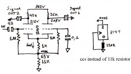
I many times use a Schmitt phase splitter like the one in the attached picture, utilizing either 12AU7 or 12AT7 etc depending on gain structure and power output configurations. I usually get 5-10% output voltage differences between phases. I wonder if that will be helped out and match closer, if I delete the tail resistor in favor of a CCS. A LM317T can easily serve. There are better sounding CCSs I am sure, and with better HF performance, but the 317 can go directly there, avoiding cable inductance and its simple to test.
So to put my questions in order:
1. Will a CCS really help the outputs to AC match?
2. Can the plate resistors come together less than 10% in value difference with a CCS in the tail?
3. Is referencing the CCS to ground good enough, or it will be better to create a -9VDC supply off the filaments 6.3VAC secondary?
4. I am sure, some of you have CCS'd a Schmitt before. Is it an audible upgrade?
Attachments
I would rather use a MJE350 or whatever, two diodes and two resistors. Just a few more parts to work up, and is little more than a CCS with some capacitance. Linear regulators don't have very great bandwidth, and may act as resistance and capacitance in the tens of kHz. It would suffice at low frequencies, though. Okay for testing, but probably noticable in the long run.
My thoughts;
Less than 10% is negligible. I probably had this statement as a signature somewhere at some time. It deserves to be used as such. The Ten Percent Rule covers all variations in 5% resistors, variation in tubes of the same type, and even applies to hearing as well, to varying degrees. A 10% difference in grid drive isn't going to change your PP amplifier much. (It might even make it more pleasant due to the 2nd harmonic distortion!)
1. The resistors shown in the diagram are about 10% off. Very little difference should even be necessary, as the required common mode range is small and the cathode impedance (about 1/Gm: less than 300 ohms) is much less than 10% of the cathode resistor.
2. With a perfect CCS in the tail, if you draw it out I think you will find that the plate resistors must in fact be equal to have equal voltage outputs.
3. A low-dropout CCS (such as a transistor and two diodes, or alternately, the popular "ring of two", which acts similarly) will have more than enough headroom supplied by the tubes' bias. Frame grid (high Gm) types may be a bit low for comfort. You aren't going to hurt anything using the bias; you have the bonus of grounding the filament winding, a common source of noise.
4. I once tried a similar circuit in Frankenhouse. I decided the preamp + cathodyne topology works better. In other situations, LTPs are extremely useful. YMMV.
Tim
Thanks!
So to put it in a nutshell:
1. Will a CCS really help the outputs to AC match?
---- Yes it will. Thought perfect matching may not be the holly grail.
2. Can the plate resistors come together less than 10% in value difference with a CCS in the tail?
---- They must be identical with a CCS in the tail.
3. Is referencing the CCS to ground good enough, or it will be better to create a -9VDC supply off the filaments 6.3VAC secondary?
---- If the 6V developed on the common 1k cathode resistor is enough for the chosen 6mA CCS circuit to operate, the ground is ok to ref the CCS. The CCS just replaces the 11k tail resistor on the schematic. A negative PSU reference won't hurt either.
4. I am sure, some of you have CCS'd a Schmitt before. Is it an audible upgrade?
---- It will certainly work with LM31T, but a good audible upgrade calls for a BJT CCS.
Yes. Bass in particular is improved.4. I am sure, some of you have CCS'd a Schmitt before. Is it an audible upgrade?
No, LM317T won't work at all well with its poor HF response. You'd be beter off keeping the 11k resistor!---- It will certainly work with LM31T, but a good audible upgrade calls for a BJT CCS.
A dual transistor 'cascode' or a ring-of-2 CCS will operate well in your circuit without any need for a negative voltage rail.
The forced symmetry that occurs when a CCS is in the tail of a differential splitter is of considerable benefit.
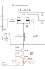
The AC impedance of the current sink should be HIGH. Cascoded BJTs, cascoded FETs, and pentodes do quite nicely. Look at the "El Cheapo" schematic, for an example of cascoded FETs.
Using a B- supply allows some coupling caps. to be eliminated. That's always a good thing, and can be essential, when loop NFB is employed.
I've done a couple of these. (Schmidt I and Schmidt II)
They work just great, with no discernable difference between phases when o'scoping the outputs. In both cases, I did the CCS from cascoded small signal BJTs. The BJT has a very high gain, and so makes a CCS with a very high impedance. Cascoding also helps to reduce the tendency for high frequency AC to flow around the CCS, which defeats the purpose. It's simple, and works great. Use the 1.0% precision metal film resistors, and you don't even have to bother to match these. Beats using a tail resistor and trying to balance outputs by unbalancing plate resistors. Also prevents unbalanced harmonic distortion as well.
They work just great, with no discernable difference between phases when o'scoping the outputs. In both cases, I did the CCS from cascoded small signal BJTs. The BJT has a very high gain, and so makes a CCS with a very high impedance. Cascoding also helps to reduce the tendency for high frequency AC to flow around the CCS, which defeats the purpose. It's simple, and works great. Use the 1.0% precision metal film resistors, and you don't even have to bother to match these. Beats using a tail resistor and trying to balance outputs by unbalancing plate resistors. Also prevents unbalanced harmonic distortion as well.
Wavebourn said:Resistance of a plain resistor is less frequency dependent.
Also, is it for instrumentations, or for listening? If for listening, does that last tiny drop of power efficiency really matter?
Its for listening. I am happy enough with its current sound. Still I like to experiment for improvement and knowledge. Many prefer it with a CCS apparently. In first opportunity I will check it out and see if I prefer it too. I have been told that perfect active phase splitting can lead to 'dry' sound in a PP amp as well.
And a thought:
A thing that I know about the cathode coupled phase splitter that I use, is that it counts on the small imbalance of its plate resistors hence of the 2 tube currents too, so they will not cancel out, and can always a signal residual exist to cathode drive the second tube. A CCS can linearize μ and rp variations and bring performance benefits, but if the plate resistors become equal as pointed out, will the circuit still be working? Its not an LTP. It does not amplify inputs difference. It amplifies SE, ground referenced, AC coupled signal.

It amplifies SE, ground referenced, AC coupled signal.
salas,
The beauty of a CCS in the tail is that it FORCES the cathode coupled pair to function as a differential amp. Of necessity, the 2 triodes move in lock step. When the instantaneous current in 1 triode increases, the instantaneous current in the 2nd triode must decrease. Cap. coupled SE drive and the non-inverting grid grounded doesn't matter. The block produces 2 equal, but out of phase, signals that is a multiple of the difference between the signals present at both grids. With the non-inverting grid grounded, only the signal at the driven grid contributes to the O/P.
In "El Cheapo", loop NFB is applied to the non-inverting grid. The forced symmetry from the CCS holds everything together. Frankly, I don't think this method of NFB would work well with a resistor of reasonable value in the tail.
FWIW, Allen Wright of VSE loves forced symmetry.
Hope it does not sound strained like an SS big amp.
No way, Jose!
 It sounds GOOD.
EC8010 said:3. Yes, but only if there really is 65V on the cathode (which there won't be because you AC coupled to the previous stage). DC couple.
''Yes'' regarding the ground, or the -PSU?
If I cant DC couple? Can I retain the 11k, tie a 6mA CCS under it and to ground, so the 65V will remain?
Miles makes a good point in his post above. Cacaded BJTs make a current source which works (maintains high AC impedance) to much higher frequencies.
I use a diff amp front end in my "Baby Huey" design. I started off with a single BJT current source. Changing to cascaded BJT made a significant improvemment, most noticable as a much more refined and detailed high frequency performance and not surprisingly, in a stereo set up, gave much better stereo imageing.
Cheers,
ian
Apart from any other consideration ( frequency response ,
bandwidth , sonic effect , etc, etc ) you can not use the
LM 317 , in this particular case , because it can tolerate
only 40 Volts CC , between the input and output terminals ,
and the design has 65 V CC .
Regards,
Carlos
bandwidth , sonic effect , etc, etc ) you can not use the
LM 317 , in this particular case , because it can tolerate
only 40 Volts CC , between the input and output terminals ,
and the design has 65 V CC .
Regards,
Carlos
The only reason there is 65v is because the current of the LTP, which is set by the bias resistor, is forced to flow through the 11k resistor. If that resistor is not there, whatever replaces it will cause a voltage drop of some magnitude.
But I was wrong, in my earlier response, to say that an SS CCS would work in the circuit as it stands without a negative rail. Something needs to set the voltage at the cathodes and there are three options, all of which require the bias resistor to be dispensed with and a single grid 'leak' resistor to be connected between the grids:
1. Keep the input coupling cap and set up a potential divider from B+ to ground, with the lower resistor bypassed by a cap and the junction of the resistors connected to the grid that is 'grounded'.
2. If there is no prior stage, get rid of the coupling cap, ground the right-hand grid and use a negative line for the CCS.
3. If there is a prior stage, direct couple to it, or couple using an RC step network, to drop the DC voltage to a sensible level without attenuating the signal.
- Status
- This old topic is closed. If you want to reopen this topic, contact a moderator using the "Report Post" button.
- Home
- Amplifiers
- Tubes / Valves
- Schmitt & CCS