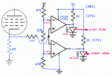
I found this circuit online....
You would not use '741 because...
Smart modern people have forgot how to use '741
The Vos is a bit high for this application
The input stops working ~~2V above the negative supply rail (we want less)
You can hardly get a '741 today; the few left should be saved for people who need them
There are cheaper better modern parts
The LM339/LM393 is perfect. Costs pennies, current production (DIP may be old stock). Inputs go all the way to the negative rail. Output is open-collector which allows logic tricks.
The rig below shows red if too hot, turn-down now! Yellow if too cool, no panic, turn up for best sound. When right, it is dark, except signal peaks may flicker.
Attachments
Why not engineer a complete regulated bias adjustment?
It is better to have knobs and lights.
It is better to have knobs and lights.

You can use a on/off switch and use leds anyway.
If we are having to set the fixed bias on tubes, don't we need to check them as the tube ages.
And if we have to set them to less negative as the tube ages, don't we have less max power from the amp, and potentially more distortion. Is it not just time to replace the tube(s)?
Self Bias requires a resistor (or current source) for each tube, and a bypass capacitor for each tube, unless we are cathode coupling with a current source. We can have a test point for each cathode, or for parallel cathodes.
This way, we can check the cathode voltage easily over time (unless we are too lazy).
It takes a $10 DMM.
You might even find it varies due to time of day, etc., according to the electric power delivered to your power outlet (unless everything is regulated, B+ and filaments).
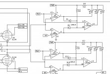
I’ve drawn up a circuit that works really well, it indicates low, high and balanced
Bias. There are two 10k pots that calibrate the window comparators, will have its own power supply, and can connect from a tap off heater winding.
YouTube
Bias. There are two 10k pots that calibrate the window comparators, will have its own power supply, and can connect from a tap off heater winding.
YouTube
Attachments
Last edited:
Looks good! I see only a part of the schematic, but if I understand it correctly, Ref is the upper threshold and WV the lower. Depending on the supply voltage, R23 and R24 may have to be changed to stay below the LM339's maximum output current.
Yes, In the YouTube video I posted I was using a 5volt DC Power source,so I used 330R for the limiting resistor. The neat thing is even if the upper and lower window are very close together
Let’s say 650mV and 600mV are my window, the green LED doesn’t shut completely off but the High and Low LEDs are completely off when the target voltage is reached.
Last edited:
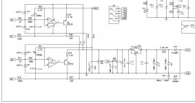
I’ve also been working on a bias control circuit to use in conjunction with the bias monitor, I’m looking at a couple of different designs, to see which one works
Best. I’ll prototype this using my ST-70 to see how it works. It does a pretty good job in B2 Spice, so I’m excited!
Best. I’ll prototype this using my ST-70 to see how it works. It does a pretty good job in B2 Spice, so I’m excited!
Attachments
Yes, In the YouTube video I posted I was using a 5volt DC Power source,so I used 330R for the limiting resistor. The neat thing is even if the upper and lower window are very close together
Let’s say 650mV and 600mV are my window, the green LED doesn’t shut completely off but the High and Low LEDs are completely off, and the green is fully lit when the target voltage is reached.
I have to object to the working principle. This design starts fresh each time theI’ve also been working on a bias control circuit to use in conjunction with the bias monitor, I’m looking at a couple of different designs, to see which one works
Best. I’ll prototype this using my ST-70 to see how it works. It does a pretty good job in B2 Spice, so I’m excited!
amp is turned on, it has no memory of previous bias settings. Thus it won't
detect tubes that starts to fail, and it does not seem to have any provisions to
indicate that a tube finally has failed.
The "right thing" should imho be a device with a memory , that has a history
of changes needed, ignoring day to day fluctuations but remembering trends.
When an amp is turned on the previous bias should be a starting point, and
during usage it should turn an alarm if bias starts to drift i.e. redplating
occuring. At such an occation it should have the possibiliy to turn off
the amp while still the "device" should be alive and displaying what
occured.
It all circles around a microprocessor powered by it's own power.
Using an analogue servo that continously adjust bias without history
is worse the a user that connects a dvdm and adjusts a pot since the human
user would have a memory of past adjustments.
Sorry to be negative, but i think the analogue approach is a dead end.
I have to object to the working principle. This design starts fresh each time the
amp is turned on, it has no memory of previous bias settings. Thus it won't
detect tubes that starts to fail, and it does not seem to have any provisions to
indicate that a tube finally has failed.
The "right thing" should imho be a device with a memory , that has a history
of changes needed, ignoring day to day fluctuations but remembering trends.
When an amp is turned on the previous bias should be a starting point, and
during usage it should turn an alarm if bias starts to drift i.e. redplating
occuring. At such an occation it should have the possibiliy to turn off
the amp while still the "device" should be alive and displaying what
occured.
It all circles around a microprocessor powered by it's own power.
Using an analogue servo that continously adjust bias without history
is worse the a user that connects a dvdm and adjusts a pot since the human
user would have a memory of past adjustments.
Sorry to be negative, but i think the analogue approach is a dead end.
A design maybe using a micro controller instead of an opamp?
This is still a work in progress, there are a few changes in order, possibly changing the overvoltage protection, shunting the overvoltage to ground,instead B+?
Here is my "Bias needs adjusting" LED indicator board. The LED will tell you which is the "problem" tube.
Uses jumpers on the board for bias setup and number of tubes to monitor.
For push-pull it compares the tube pair for current imbalance of > 5%
;Tube Current Monitor with Delay and Soft Start.
;Will monitor one or two pairs of Push Pull tubes or one or two Single Ended tubes
;using the 1.024v fixed voltage reference and A/D converter in the pic 16F1825
;J1 ON J2 OFF = Calibrate PIC A/D value and set up amplifier. GREEN LED will flash (Stores calibration value)
;J1 OFF J2 ON = run with Two Tubes Push Pull. YELLOW/GREEN LED will flash until one tube reaches
;95% of calibration value then begin monitoring for difference between tubes.
;More than 10% difference between tubes = Shut Down.
;NOTE: YELLOW RED BLINKING LED indicates tube pair is more than 5% out of balance.
;Number of RED blinks is tube number of tube that is 5% too high. Example:
; Yellow-Red-Red Yellow-Red-Red pattern means Tube TWO is biased over 5% higher than
; Tube One
;SOLID GREEN LED indicates less than 5% out of balance between monitored tubes
;J1 and J2 OFF = run with Four Tubes Push Pull. YELLOW/GREEN LED flashes until one
;tube reaches 95% of calibration value, then begin monitoring for 10%
;difference between tube pairs. YELLOW LED indicates a tube pair is more than
;5% out of balance as above.
;Solid GREEN LED indicates less than 5% difference in current between pairs.
;*************SHUT-DOWN**************
;If amplifier shuts down it will blink out which tube caused the shut down. EG.
;RED-RED-YELLOW-YELLOW-YELLOW RED-RED-YELLOW-YELLOW-YELLOW repeating means Tube 3 went too HIGH!
;Number of YELLOW flashes is Tube number
;J1 and J2 ON = NO current monitoring LED Solid GREEN
;J1 and J2 Jumper sideways = Monitor One or Two Tubes SINGLE ENDED.
;tubes must stay between 50% and 130% of calibration value or will Shut down.
;Delayed Start Adustable from 0 to 120 seconds Yellow LED flashes 1 sec. intervals
;Adjust start delay with 10k Pot. 0 ohm = no delay 10k = 2 minute delay
Attachments
- Status
- This old topic is closed. If you want to reopen this topic, contact a moderator using the "Report Post" button.
- Home
- Amplifiers
- Tubes / Valves
- LED bias indicator