I am sure that there is something fundamental about the hum in my Aikido. Before going exotic, I want to be sure that the basics are correct (as far as is possible).
I experimented with a cheater plug on the Aikido and then on my main amp. The level of hum was further diminished by doing this becomming barely audible from the nearly barely audible prior. OK, this implies that I have a ground loop that is having an effect.
My concern lies with ensuring that my PSU and PCB are connected correctly.
My current configuration is to take the PSU GND and connect it to the GND pad of the PCB. From their I connect to chassis earth - thereby connecting both PSU and PCB to earth.
This is shown in the first diagram. In the PCB instructions John Broskie says that the PCB can be floated, jumpered to the chassis via J7 and the mounting bolt, or floated using a small value cap. However, in my current configuration, floating the PCB means that the PSU is also floated and that is not good, is it?
So, should things be wired as in my second diagram?
Thanks,
Charlie
Attachments
I like neither of your solutions. Since I obviously assume that Broskie's PCB is designed properly to avoid ground loops, I would attach the PSU B+ and ground wires to the PCB, and then bond that PCB to the chasis via either the jumper and bolt or a separate wire from the PCB grounding land.
EDIT: stupid me, that is option #1, didn't see it right away
EDIT: stupid me, that is option #1, didn't see it right away
Leadbelly,
I am glad that you agree with one of my wiring diagrams, so my current configuration is probably correct. I do notice that both the filament transformer and the B+ transformer (I have separate ones) do begin to buzz when power to the latter is applied. It is not clear exactly which one of the two transformers is actually buzzing, but the transformer buzz is equally present when I put my ear to either trafo. I expect that it is this buzz that is being transmitted on the signal.
When power is applied to only the 6.3V filament trafo, it does not buzz at all. Only when B+ is applied. This leads me to think that the B+ trafo (or B+ PSU) is causing the buzz, and that it is being passed onto the filament trafo via the 1/4 B+ voltage reference (subject of an earlier post).
What I can do is to replace the 125-0-125 with a 275-0-275 and a quick rewire to use full-wave tube rectification. My 275-0-275 is one of the 300 series from Hammond rather than the slightly lower quality 200 series which is my 125-0-125. The 300 series can also be wired for 120V, which my current trafo can't and it tends to see 124V on the 115V rated primaries.
You know, I should simply stop worrying about all of this. I have a great sounding Aikido preamp. The truth is that the hum is only audible when everything is really, really quiet and my ear os close to the speakers. At some point, I'll rehouse my Aikido and use aluminum for the chassis plate rather then the steel used at present. That'll also be the time to change out the trafos.
Charlie
I did have some communication with John Broskie and he was very helpful in suggesting that hum was a bane for many designers and that he has also had some problems with it in other projects.
Sy, Excuse my ignorance, but what are the "nulling" resistors? Are these resistors R15 and R16 in Broskie's design? They are in series between B+ and GND in the following configuration: B+ - C6 - R15 - R16 - GND. I cannot remember my exact values, but I think I have C6 = 0.1uF; R15 = 82K; R16 = 100K.
If these are the actual values would trimpots work here?
Charlie
Yes, R15 and 16. I subbed a trimmer combo for R15. You could just use a trimmer rated at something higher than the optimum value, but to minimize the sensitivity of the adjustment, you'll probably want to have a series resistor make up a portion of that- if your range goes to 20% over and under the theoretical value, that should cover most tube variations.
For example, let's say that R15 is theoretically 90K. I'd use a 75k resistor in series with a 25k trimmer.
For example, let's say that R15 is theoretically 90K. I'd use a 75k resistor in series with a 25k trimmer.
Thanks Sy,
I'll do as you recommend. However, I'll first go and check my actual values against the newer version of John Broskie's PDF instructions as he gives firmer values for these resistors for specific tubes.
I really cannot tell the frequency of the hum anymore, it is really that quiet. My gut feeling is that it is 60Hz. BUT buzzing transformers will likely do so at 120Hz. Either way, replacing R15 with a resistor/pot combo is hardly going to break the bank!
Charlie
Fred,
As I have read, 60Hz sounds pretty low and dull, while 120Hz sounds more raspy. One thing I did was to download a freeware signal generator for my Mac and played sine waves at these frequencies. The problem with the hum from my Aikido is that it is so quiet that I really cannot tell which of the two frequencies it most resembles! I mean, everything has to be dead quiet - no AC, ceiling fan or cycling fridge in order for me to hear the hum from further than 8 inches from my speakers. BUT I know it is there! It was worse when I used a voltage divider on my attenuator to give more useable steps. When I moved the divider into my main amp, the hum was significantly less and I have no idea why!
I am very flattered that my blundering about with my Aikido has resulted in useful threads. I would really recommend care in placing of your components, especially your signal wiring and ground wiring. When I finally get around to re-housing mine, I'll pay lots of extrat care to component placement.
Good Luck.
Charlie
Hi Charlie,
I am still quite new to DIY and have built only a few preamp's from scratch and rebuilt/restored a couple tube amp's. Hum is my biggest enemy that I just can't conquer. My results are very inconsistent. Some I was able to fix, some were hum-free at the beginning, and some just never go away. My recently built FVP5 clone from Shoog has a residual hum that I simply couldn't get rid. I used the same trick on my amp side to reduce the input sensitivity so that I don't really hear the hum unless my ear is within 6 inches from the speaker. It looks like your xformer buzz is a bigger distraction than the hum. I may sound crazy, but did you try simple AC heater with the center tap connected to the 1/4 B+? I had regulated DC heater supply for my FVP5 at the beginning. In the hum hunting process, I got rid of the regulated heater supply and found the noise was lowered!! So, it is definitely worth to try if you haven't especially you are going to recase the Aikido.
Cheers,
Charlie,
You may think it's blundering (and it may well be) but you are far from alone in your quest for knowledge. I too, am building an Aikido PCB, only 9 pin version. (I've jumped into a couple of your other threads)
In regards to the Biasing of the heater voltage to the B+ rail:
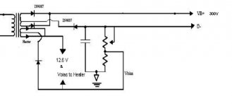
I understand using the voltage divider to get the 1/4 B+, but is that line then used for the (-) side of the heater supply? I am using full wave rectification on my B+ but Bridge rectification on the heater supply, I have CTs on all my Transformer outputs.
If I use the 2 (+) from the 6.3V windings tied together that will get me 12.6V, would I tie the 1/4 B+ to the CT of my 6.3? Or do I cap off the CT and use the 1/4B+ as my return? I want to use the 12.6V option as it will allow me to later change tube heater voltage to 6.3V with the jumpers. If I indeed want to try different tubes.(trying to think ahead)
Sy,
It was a pleasure to meet you (Stewart) at BA in S.F., Thank you for all you help (past and future). The RED LIGHT DISTRICT isn't nearly as dodgy as you made it out to be. Great Sound too! I appreciate your patient help and that you can break it down to lay terms for me and others new to valves. Good tip on the 1/4B+ VR. I hope you are enjoying your trip to Europe. I miss France and Northern Italy. Gorgeous.
Ron
cbutterworth said:
I am very flattered that my blundering about with my Aikido has resulted in useful threads.
You may think it's blundering (and it may well be) but you are far from alone in your quest for knowledge. I too, am building an Aikido PCB, only 9 pin version. (I've jumped into a couple of your other threads)
In regards to the Biasing of the heater voltage to the B+ rail:
I understand using the voltage divider to get the 1/4 B+, but is that line then used for the (-) side of the heater supply? I am using full wave rectification on my B+ but Bridge rectification on the heater supply, I have CTs on all my Transformer outputs.
If I use the 2 (+) from the 6.3V windings tied together that will get me 12.6V, would I tie the 1/4 B+ to the CT of my 6.3? Or do I cap off the CT and use the 1/4B+ as my return? I want to use the 12.6V option as it will allow me to later change tube heater voltage to 6.3V with the jumpers. If I indeed want to try different tubes.(trying to think ahead)
Sy,
It was a pleasure to meet you (Stewart) at BA in S.F., Thank you for all you help (past and future). The RED LIGHT DISTRICT isn't nearly as dodgy as you made it out to be. Great Sound too! I appreciate your patient help and that you can break it down to lay terms for me and others new to valves. Good tip on the 1/4B+ VR. I hope you are enjoying your trip to Europe. I miss France and Northern Italy. Gorgeous.
Ron
Renron,
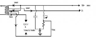
The second diagram.
This is essentially a full wave rectification. I am not sure how do you get 12.6V and the B-. Anyhow, I won't bother to add a tuning pot there because the 1/4 voltage divider doesn't have to be that accurate. Use the 6SN7GTB as an example, the +ve and -ve cathode to heater voltage limit is 200V. Let say you have a 400V B+, then the voltage of the cathode of the top triode is roughly a little above 200V which just exceeds the limit. So, you create a voltage divider off the B+ to float the heater. In this case, anything near 100V (1/4) will bring the difference within limit, +/- a few volts is fine. I hope this will help.
No, i think the second one is wrong too.
The voltage divider:
The "leg" with the pot/resistor for the voltage divider should be attached to the B+ line. (thats the one on the RHS in the diag)
The other "leg" (LHS) with the capacitor should be connected to B-.
So the voltage divider is across the B+ and B-. If there were no resistors you would have the full B+ voltage - a direct short. With the resistors in place the voltage is divided so that in between the 2 resistors you get a voltage that is 1/4 of the B+ voltage. The pot allows you to vary one of the resistors so that you get exactly 1/4. A poster above mentioned that this isn't all that critical, but if you have the pot you might as well use it. You can try varying the pot, hence the floating voltage level for lowest hum.
Fran
EDIT: Your drawing of the pot in the second diag is a bit screwy. I think if you just used a resistor of about the right value it would be easier. As shown you have 3 resistors in there, when you only need 2.
- Status
- This old topic is closed. If you want to reopen this topic, contact a moderator using the "Report Post" button.
- Home
- Amplifiers
- Tubes / Valves
- Wiring PSU and Aikido PCB