I love the way people call designs like this grounded grid, it's not - it's a really lousy long tailed pair, aka a differential amplifier stage.. It's even drawn in such a way as to mislead. Argh!!!!!!  I designed and build stereo pre-amplifiers 20yrs ago with a considerably better implementation of the differential amplifier than used here. It's OLD HAT!
As an aside for the amount of gain it provides it is needlessly complex - you can do it all with a single tube like the 12B4, if you need a little more gain a single 5687 will do the job very nicely...
I designed and build stereo pre-amplifiers 20yrs ago with a considerably better implementation of the differential amplifier than used here. It's OLD HAT!As an aside for the amount of gain it provides it is needlessly complex - you can do it all with a single tube like the 12B4, if you need a little more gain a single 5687 will do the job very nicely...
HollowState said:Haha! It's not even a lousy short tailed pair since the first triode's plate is at AC ground and trying to work as a cathode follower into an impractical 500 ohm load.
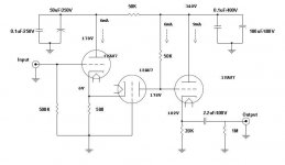
rdf said:Operating points are wrong, 6ma across 50kohm = 300 volts. No way the plate is 178 vdc at that current/load.
Even more duhhhh!

There is nothing differential about this circuit .....
I don't even see a "long" tail .........just a common cathode for both stages....
You have a cathode follower input stage driving a grounded grid stage..... this is done since both of these stages have mucho low Miller effect....so the high frequency is more linear for audio or RF applications....
But this is in vain, since the 3rd stage is the weak link since it has less bandwidth than the preceeding stages......
Also the circuit values are FUBAR.....
Chris
I have little experience of playing with tubes, and I know that kevinkr, who has very much more expereince, has noted it as a poor long tail pair.
However to these eyes it looks like a cathode follower input in order to impedance match to a wide bandwidth true-grounded-grid amplifier feeding into a cathode follower to impedance buffer the output.
From what I read of the relative merits of cathode follower and grounded-grid stages, this circuit topology seems conceptually OK for a wide and flat frequency response into reasonable loads.
Might it be possible with some optimisation to be a practical wide bandwidth low distortion line amplifier? Perhaps keeping the general topology, but changing the tube types, R and C value changes and introducing a constant-current load to the final cathode follower?
Just curious...
cerrem said:There is nothing differential about this circuit .....
I don't even see a "long" tail .........just a common cathode for both stages....
You have a cathode follower input stage driving a grounded grid stage.....
A "cathode follower input stage driving a grounded grid" is a differential amp. And, yeah, you don't see a long tail because there isn't one. As for the actual topology, the way the schemo was drawn tends to make it less obvious as to what it really is. You can take our word for it: it's a differential.
When using BJTs, you can get away with using short "tails" since these devices have inherently large gains. The 12AU7, however, is not a high gain device, and it will require a much longer tail. This entire design looks like it was done by someone with more solid state experience than hollow state. It would work much better if that 500R common cathode resistor were to be replaced by a solid state CCS, or at least a much larger resistor connected to a negative rail.
Miles Prower said:
A "cathode follower input stage driving a grounded grid" is a differential amp. And, yeah, you don't see a long tail because there isn't one. As for the actual topology, the way the schemo was drawn tends to make it less obvious as to what it really is. You can take our word for it: it's a differential.
I'm sorry, but with all due respect I disagree and will not take your word for it..... I am aware there isn't a Long Tail....that is what I originally stated...
Prove it....show the differential equations and solution for the circuit as a differential amp...
Chris
What's all the fuss? As cerrem said, the radio guys commonly drove a grounded grid stage with a cathode follower. Though I'm no radio guy, the direct coupled circuit at the top of the thread seems fairly typical. The grounded grid has a very low input resistance and the cathode follower has a very low output resistance. The combination is one of those elegant solutions that apparently works very well. Having said that, I'm sure I've seen slightly more complicated implementations that provide a better load for the cathode follower, though I don't recall how it's done.
It does look superficially like a poorly implemented LTP but that's not how it's intended to be used and thinking of it in those terms will not lead to enlightenment.
As for the sound, I can't comment.")
It does look superficially like a poorly implemented LTP but that's not how it's intended to be used and thinking of it in those terms will not lead to enlightenment.
As for the sound, I can't comment.
http://www.audioxpress.com/magsdirx/ax/addenda/media/muhammad.pdf
Interesting article on large signal analysis of tube based differential amplifiers... Using the equations provided in this rigorous article you can analyze the differential behavior of the circuit at the beginning of this thread or for that matter any other you choose to.
Interesting article on large signal analysis of tube based differential amplifiers... Using the equations provided in this rigorous article you can analyze the differential behavior of the circuit at the beginning of this thread or for that matter any other you choose to.
- Status
- This old topic is closed. If you want to reopen this topic, contact a moderator using the "Report Post" button.
- Home
- Amplifiers
- Tubes / Valves
- grid-grounded preamp sound