EF86.
Looks while worth a try concepually. I have all those bits in my junk box (and no transformer)
A trick with pentodes with separtely pinned suppressor grids is instead of tying it to the cathode, is to tie it 2-3V below the cathode (a 3.3V 1.2 AA computer battery would work here.
Th etechnical reasons made sense to me, don't ask me to remember what they were.
dave
I may try building this circuit with the 6AQ5. I have heard people having great success with the 6V6 as a preamp tube, and the 6AQ5 is the miniture 7pin version.
I have a version of this amp at the moment using all PCC88's and a mosfet as the top element of the totem. It sounds very good, but I want to replace the mosfet and run more current through the totem. Also what I really want is for a sound with a touch more bottom end grunt and the 6AQ5 may just bring this. If the UL connection doesn't work as expected I can simple triode it and nothing is lost.
Shoog
Good to hear a thumbs up.
I was looking at the 6AQ5 and the curves start to look very squashy down at those plate and g2 voltages. However the 6AU6 looks very linear and happy at this sort of operating point.
The only real questions I have are;
1: is the gain going to be excessive (the 6AU6 is 36x in triode mode)
2: is its performance going to be superior over a simple triode
The only way to answer the second question would be to build it I suppose.
Shoog
I just happened across the data for the ECF83. Looks as if it might be an excellent candidate for this application.
The Pentode section has a gain of 11x in triode mode at -4V bias and 5mA current.
The Triode is capable of 10mA at 80V. This means it could be used as the CCS on the bottom of the totem, and it would perform better than the ECC88 because its grid bias would be 4V rather than the 1.5V or so of the ECC88.
The other main advantage is that this then becomes a two valve design with at least one of the valves been cheap.
Shoog
Shoog,
My first post here in a long time... much too busy...
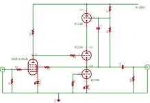
Interesting circuit. As Jan said, this is really a triode circuit. You can think of it as UL with a 97% (or so) tap, and that's really a triode connection after all. However, there is one difference here: the screen current (both DC quiescent and signal) flows through the CF cathode (V2A), and not through the plate load resistor (R3) as you'd usually see with a screen connected directly to plate. This means that the small contribution to overall transconductance from the screen will be lost. So you'd have maybe 80% of the regular triode-connected transconductance available, with a similarly slight increase in rp. I don't think this a problem, and it's hard to say which connection might be better with regard to distortion and sonics. It's easy to switch back and forth. I think it's worth a try.
If you want the DC quiescent plate voltage to be higher than the screen voltage for a particular pentode, you could slip a zener or a stack of LEDs between the CF cathode and the screen, and readjust B+ accordingly. Zener noise could be problem, but probably not too bad at this point. Bypass it heavily.
Finally, if you want the bottom tube (V2B) to act as a good CCS, then perhaps this isn't the best place for LED cathode biasing. LEDs are used in cathodes to give low resistance and low feedback. Here, you should use an unbypassed cathode resistor for high feedback; its value gets multiplied by mu+1 to add the to the plate resistance, making it a better CCS. You could even put a solid-state CCS in the cathode to really pump it up and to allow for precise settability.
Let us know how it plays out.
My first post here in a long time... much too busy...
Interesting circuit. As Jan said, this is really a triode circuit. You can think of it as UL with a 97% (or so) tap, and that's really a triode connection after all. However, there is one difference here: the screen current (both DC quiescent and signal) flows through the CF cathode (V2A), and not through the plate load resistor (R3) as you'd usually see with a screen connected directly to plate. This means that the small contribution to overall transconductance from the screen will be lost. So you'd have maybe 80% of the regular triode-connected transconductance available, with a similarly slight increase in rp. I don't think this a problem, and it's hard to say which connection might be better with regard to distortion and sonics. It's easy to switch back and forth. I think it's worth a try.
If you want the DC quiescent plate voltage to be higher than the screen voltage for a particular pentode, you could slip a zener or a stack of LEDs between the CF cathode and the screen, and readjust B+ accordingly. Zener noise could be problem, but probably not too bad at this point. Bypass it heavily.
Finally, if you want the bottom tube (V2B) to act as a good CCS, then perhaps this isn't the best place for LED cathode biasing. LEDs are used in cathodes to give low resistance and low feedback. Here, you should use an unbypassed cathode resistor for high feedback; its value gets multiplied by mu+1 to add the to the plate resistance, making it a better CCS. You could even put a solid-state CCS in the cathode to really pump it up and to allow for precise settability.
Let us know how it plays out.
Hi Brian,
Good to hear from you. I'm using your idea for Constant Current Sink differential stages extensively now - to very good result. Just built a headphone amp and used it, and also intend to use it in a Tabor clone. Thanks. The only variation I am trying is cross coupled resistive garter Bias which eliminates the CCS.
I have used a LED in this position in my current preamp, and it works well. However your explanation clarifies whats going on and leads me to think this is not the best choice, so I will go for a resistor.
I have done some research on the ECF83 and its a perfect fit for this application, with one cavite. That been that the pentode is remote cutoff (not so good). However looking at the curves, if I have it set up with the screen and plate at 80V and the bias point at -4V, the input signal will be about +/- 1V and that is just out of the cut off region. Its certainly worth a try as this operating point is tailor made for the Super Linear buffer. Also both the triode and pentode are happy to pass reasonable current (7-10mA) which is unusual for a combination valve. Its other main advantage is the pentode has a gain of only 10x in triode mode, which is again unusual for anything but a power pentode - and perfect for this application.
I'm just working on ordering a pair of ECF83's.
Shoog
Good to hear from you. I'm using your idea for Constant Current Sink differential stages extensively now - to very good result. Just built a headphone amp and used it, and also intend to use it in a Tabor clone. Thanks. The only variation I am trying is cross coupled resistive garter Bias which eliminates the CCS.
Finally, if you want the bottom tube (V2B) to act as a good CCS, then perhaps this isn't the best place for LED cathode biasing. LEDs are used in cathodes to give low resistance and low feedback. Here, you should use an unbypassed cathode resistor for high feedback; its value gets multiplied by mu+1 to add the to the plate resistance, making it a better CCS. You could even put a solid-state CCS in the cathode to really pump it up and to allow for precise settability.
I have used a LED in this position in my current preamp, and it works well. However your explanation clarifies whats going on and leads me to think this is not the best choice, so I will go for a resistor.
I have done some research on the ECF83 and its a perfect fit for this application, with one cavite. That been that the pentode is remote cutoff (not so good). However looking at the curves, if I have it set up with the screen and plate at 80V and the bias point at -4V, the input signal will be about +/- 1V and that is just out of the cut off region. Its certainly worth a try as this operating point is tailor made for the Super Linear buffer. Also both the triode and pentode are happy to pass reasonable current (7-10mA) which is unusual for a combination valve. Its other main advantage is the pentode has a gain of only 10x in triode mode, which is again unusual for anything but a power pentode - and perfect for this application.
I'm just working on ordering a pair of ECF83's.
Shoog
I have been using this type of circuit for some time, it works quite well. Put a CCS in the pentode plate circuit for very low distortion. Some voltage dropping devices for the screen grid will keep its current more linear (which is helpful since it subtracts out from the plate current).
If you use a low capacitance MosFet for the follower part (Fairchild FQP1N50), there is no need for the CCS output follower load (or the top plate follower either) due to the Fet's very high gm.
http://www.diyaudio.com/forums/showthread.php?postid=1172104#post1172104
It can also be used to make an all SS "Early-effect triode" device by using a Fet cascoded bipolar device in place of the pentode. (The FET gate then becomes the "screen grid" for feedback) Higher Beta transistors give a lower Mu triode as a thinner base region has a larger base width modulation Early effect. Quite linear triodes are possible. I use this technique in a no GNFB SS "Early-effect triode" amplifier.
http://www.diyaudio.com/forums/showthread.php?postid=1258784#post1258784
Don
Shoog,
A sort of j-vector question from a different angle. Sure it will work ...
but why does one want to look at this instead of say a pentode + cathode follower/bootstrap topology? It would naturally depend on the output required; how much signal do you want out? If this is to feed any normal power amplifier (i.e. for some few volt out), I would need to be convinced that the audible improvement would merit the added complexity.
What am I missing?
Johan,
In answer to your point, I agree that the improvement may just be marginal. It also puts sever limitations on the pentode in order not to produce excessive gain. There is also the issue that the screen current will tend to delinearise the CCS operation of the buffer.
So it may just be a fools errand. Still I am interested in the difference that a small signal pentode will bring to the mix, and there is the potential for it to have vanishingly small amounts of distortion.
Curioscity really
Shoog
Shoog said:Curioscity really
I think that's plenty good enough, except for the spelling
It seems to me that we can approach any project with either, or both, of two objectives:
1.) To make something that sounds "good". To that end we could safely pick any one of the many existing designs or design approaches to build.
2.) To experiment with something new, possible stumbling on something to advance the art. Like mutations, the odds of a new configuration being superior to the tried-and-true are pretty low, but experimentation is a noble effort on its own.
Having said that, I will say that I would expect higher distortion from LARGE signals with Shoog's configuration. The sum of plate current plus screen current (that together would flow through the plate load resistor in a conventionally triode-converted pentode) is more nearly constant than plate current alone. At low plate voltage swings, the screen current jumps up while the plate current falls. BUT we're dealing with a preamp here, and an operating point can easily be selected to avoid the low plate voltage region. How supplying screen current separately from the plate might effect total distortion (and the distortion harmonic series) with small signals is unknown to me. Yes, the CF section also has the additional burden of driving the screen. I hope you try it and compare it the conventional case, and report your findings. Do you have a distortion meter?
Do you have a distortion meter?
Unfortunately not. I took a more conventional triode front ended version to a diyshoot out and it performed very well. I will know whether it performs better than the original simply by comparing and presenting it to the same audience.
I have decided that my preferred triode pentode combination is just to obscure for practical use. I will therefore attempt a build with a ECF80. Not quite a drop in, but good all the same(and a regarded pentode). It also has lower screen draw so should be easier on the cathode follower. The real question is what gain can I expect to get with the pentode effectively triode strapped.
Having said that, I will say that I would expect higher distortion from LARGE signals with Shoog's configuration. The sum of plate current plus screen current (that together would flow through the plate load resistor in a conventionally triode-converted pentode) is more nearly constant than plate current alone
It should only ever be presented with about a 1V signal so the issues you describe should be minimal. I believe that taking the screen current from the cathode should minimise distortion because that is exactly what the CF should be good at - sourcing current.
I am dead keen to give it a try, all that remains is to get some ECF80's.
Shoog
So I lashed up a front end with the 6AQ5. First thing, at low voltages the 6AQ5 sounds dull and bloated. It probably would sound better at higher voltages and higher currents (I was running it 5mA), also its extremely microphonic in this capacity.
Anyway I tried it with my concept and unfortunately it wasn't a great success. I tried it in normal triode mode and the UL mode. The triode mode despite the limitations of the 6AQ5 sounded smooth and detailed. The UL mode had a hard grainy edge to the treble, which was somewhat attenuated - though the bass and midrange sounded possibly better.
So the conclusion I have come to is that its a deadun, however I think there is enough merit in the idea of using the ECF80 to give that a try with the pentode triode strapped.
Shoog
- Status
- This old topic is closed. If you want to reopen this topic, contact a moderator using the "Report Post" button.
- Home
- Amplifiers
- Tubes / Valves
- An UL preamp idea.