metric vs 'imperial?' or US lamination data
Hello:
Firstly, thank you/merci to Yves for sharing his software project, and answering questions for one and all!
I have started to read the OPT-DA threads...but one (this one?) had 122 posts, so I want to ask here in case there is a quick answer...
I have figured out how to 'convert' between US EI and metric EI lamination sizes, but have a couple questions.
1) Is it possible to edit and re-save , or to create new table entries for lamination sizes not pre-loaded in the basic OPT-DA package?
2) There are in some cases multiple table entries for a given lamination size, something like, for example, (I am making this up without looking at the software), EI96, EI96H, EI96A, EI96B. I may be wrong about the exact listings, but it's the concept I would like clarified...what are the A/B/C options, stack height? If so, I imagine I could figure out from the core properties in the preloaded lamination listing, but that had not occurred to me as an answer previously. I think H might be a longer-leg E lamination, but am not really sure about the A/B/C options.
Thank you
Murray
Thank you.
Sounds like with a little digging I should be able to figure out other pre-loaded configurations in OPT-DA.
Yes, there is two ways:
The "hard" one consists in editing the file named "core.tbx" with a text editor like Notepad.
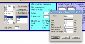
The "soft" one consists in using the integrated core editor .
To do that:
- double click in the core list on the one you want to modify
- click on the "Edit Hightlighted" button
This opens a box named "Core data" where you can enter new values.
- Afe stands for "core section"
- Mfe stands for "core weight"
- MPL stands for "Magnetic Path Lenght"
- Bobin deepth, width and mean turn lenght are self explanatory.
All the values are "metric".
Entering a new "Name" will display values for that name or create a new one if it doesn't already exists.
Ther is no "rename" function, sorry . . .
When done don't forget to save before closing (no warning message !)
When "Core data" box is closed, the core list is updated to include the new one at the right place according to the sort method set by the two buttons above the "Edit Highlighted" one.
Keep a copy of the current "core.tbx" file before stating

Comparing the content of this file and what the "Core data" box displays will reveal its meaning
Have fun,
Yves.
Attachments
Hello to all,
I used to play with OPT_da when I tried to run windows. Windows didnt work well back then, it hardly works today, and I think will be worse in future.
BUT Yvesm's little program is very accurate !!!
AT least its more accurate than my physical transformers, and I have been winding them for almost 50 years.
I used to use a winding machine, but now I wind by hand!!! its MUCH slower but far more accurate, and I can make a very good quality transformer without special tools. So can anybody here!!! the devil is in the design, NOT so much the production.
THere have been discussions on core size and stack ratios, FORGET them, just use the next biggest core ( centre leg) than what you calculate. By that I mean if you calculate 1.25 X 1.75 core, make the core 1.5 X 1.75 ( inches of course, Im old, and I learned in inches not metric).
Ill wait and see what responce I get from this post, then I will post more.
Joe
Program crash
Hi Yvesm,
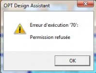
OPT_da works well, but I have a little problem, using SPICE menu.
The LTSpice simulation done (*.asc file, *.plt file, running "AC Analysis" simulation), but OPT_da give an error message, then crashing.
Do you have any suggestion?
Hi Yvesm,
OPT_da works well, but I have a little problem, using SPICE menu.
The LTSpice simulation done (*.asc file, *.plt file, running "AC Analysis" simulation), but OPT_da give an error message, then crashing.
Do you have any suggestion?
Attachments
resident,
This is based upon the Fender/Marshall winding order:
1/2 Pa
4 ohm
4 ohm
Pb
8 ohm series extension
16 ohm series extension
1/2 Pa
Bud
Bud, could you advice me how to adopt above system with only 4 ohms and 8 ohms extension?
Thanks in advance.
Adam
This is based upon the Fender/Marshall winding order:
1/2 Pa
4 ohm
4 ohm
Pb
8 ohm series extension
16 ohm series extension
1/2 Pa
Bud
Bud, is it possible to adopt the system above to apply only 4 ohms and 8 ohms extensions?
If so, then how?
Thanks in advance,
Adam
Adam,
You would need to convert the 16 ohm extension winding into an 8 ohm extension winding.
For clarity:
Assuming that you read the formula above as PA meaning one half of the initial Primary winding you would wind that number of turns, you would then wind two 4 ohm secondaries with the current load split between them but with each having the total number of turns required for the 4 ohm winding. Almost certainly this will be two windings of two layers each, for a total of four layers. Then you would wind the entire next half of the primary winding, PB. Then two 8 ohm windings that use the 4 ohm winding for part of their total needed turns count. Likely two single layer windings here and again splitting the current load and with the total number of turns needed to add to the 4 ohm winding turns, to meet an 8 ohm load. Then you would wind the remaining half of the Primary A winding.
All of the connections for the split primary A, the CT with Primary B and the finish of Primary A and primary B are made outside of the coil. The secondary connections are also made outside of the coil. It is convenient to break these wires out on opposite coil faces to make connections easier and safer.
I apologize for not responding earlier, but I no longer receive prompts for this thread, so it is good of you to PM and alert me to your need for clarity.
Bud
- Status
- This old topic is closed. If you want to reopen this topic, contact a moderator using the "Report Post" button.
- Home
- Amplifiers
- Tubes / Valves
- OPT Design Assistante (EL84)