I'm designing a 200 watt bass amp using a quad of KT88's in ultralinear configuration. I'm looking at Hammond output iron for cost / performance reasons, particularly the 1650W rated at 280 watts at full power bandwidth down to 30 Hz. At 28 pounds its a monster. I was also looking at the 1650T with the same PP impedance (1900 ohms) but rated at 120 watts, at only 9.5 pounds (not the 14 that is listed on Hammond's site).
I know people have pushed the 1650T to over 150 watts, and Kevin O'Conner has a 200 watt guitar amp in is Principles of Power book using the 1650T. I'd guess that would be fine for guitar, but not for bass. I was thinking of the possibility of paralleling two 1650T's (primaries and secondaries) which would keep the turns ratio (and therefore the impedance) the same but would effectively double the power handling and maintain full power bandwidth to 30 Hz. The seeming advantage? Price for two 1650T's is about the same as one 1650W, total weight would be around 19 lbs vs 28 lbs, and even though they would take up a bit more chassis space than the 1650W (not by much, as I said the 1650W is a beast), you could balance the weight on the chassis with the two.
Has anyone tried anything like this? I saw that John Broskie had a blog about paralleling output transformers from Dynaco ST70s to make a "super" Dynaco ST70 so I figure the idea is not too far fetched:
http://www.tubecad.com/2005/March/blog0041.htm
Are you able enough to lift it ? By the time the mains tranny is fitted you will have more than double the weight and the chassis be strong enough to take settling down thumps.
There is nothing wrong with the power tact except over 530V B+ with modern day KT88's is going to stretch them. Going for a triple per side push pull would relieve but one would up the heater current supply with larger chassis size but with more o/p tubes will tax the performance of the interstage driver. where quality isn't a issue then it doesn't matter.
Paralleling output transformers is fine (As Broskie points out) so long the specs on each are fairly sim. Any problems would come apparent at higher frequencies, as circulatorary leakage inductance / capacitance parasitics become a conflict pest. At the low f end it wouldn't be noticed and in fact many amp builders have used standard mains transformers frequencies under 500Hz. Other builders in this forum have done this.
Generally for hi-fi it is better to lower the primary side working impedance (i.e fit more tubes) which lowers parasitic problems which increases the bandwidth whereas your suggestion would not.
I use 2K A-A UL 43% 10Lb lump made by Majestic which can hull 175W at 20Hz but needs over 530V B+ to get it. The mid and bass range is incredibly forceful and dangerous. With KT88's running at this voltage with 60mA Iq per tube and 130mA on peaks, the remaining ability is on the power supply to hold up 0.75A on power peaks.
The other possibility is to build a normal stereo amp and power bridge mode the outputs by using a phasesplitter in the input. Anyone done this ?
Changing ideas, this enables you to simply revert to a standard stereo version at virtually nil expense.
richj
hey-Hey!!!,
Getting 100W/pair of KT88 is a bit of a stretch. I'd suggest a larger single pair of valves. 813 perhaps? How important is the 200W spec?
Multi-parallel pairs risks oscillation. Nearly all of the commercial stuff I've looked at has at least one countermeasure, most have a few. Extra care is certainly required for that sort of topology.
cheers,
Douglas
The way most muso's treat gear, those long 813 filaments should last several days at least.Bandersnatch said:hey-Hey!!!,
Getting 100W/pair of KT88 is a bit of a stretch. I'd suggest a larger single pair of valves. 813 perhaps? How important is the 200W spec?
Actually, both the original Genalex data sheet and the Shuguang datasheet from Pentalabs both spec a pair of KT88s at 100 watts in ultralinear with a plate supply of 560 volts (I'm assuming that's under full load, so idling would probably be 600+ V for a decent power supply) into 4.5K P-P. So a quad should be good for around 200 watts with about 2.2K P-P. The 6550W is 1900 ohms P-P so it should be doable. Yes, it's pushing the tubes a bit, but that's the challenge. Rich, maybe you're right, it would just be easier to use the 1650W and deal with the extra weight.
Using 813's while interesting, wouldn't be practical for a portable amp becuase of their size and power supply requirements. The 200 watts isn't a spec as such, but a goal. As I said the challenge is what makes it interesting. A sextet would easily provide the 200 watts conservatively except for the cost of two more tubes and the chassis area to accomodate them (the datasheet recommends 4 inch center to center spacing which is kind of largish but doable). Six would require a lot of area, unless I cheat a bit. Maybe that's OK if running them conservatively and/or using a fan? Have to think about that.
Using 813's while interesting, wouldn't be practical for a portable amp becuase of their size and power supply requirements. The 200 watts isn't a spec as such, but a goal. As I said the challenge is what makes it interesting. A sextet would easily provide the 200 watts conservatively except for the cost of two more tubes and the chassis area to accomodate them (the datasheet recommends 4 inch center to center spacing which is kind of largish but doable). Six would require a lot of area, unless I cheat a bit. Maybe that's OK if running them conservatively and/or using a fan? Have to think about that.
Bandersnatch said:
Multi-parallel pairs risks oscillation. Nearly all of the commercial stuff I've looked at has at least one countermeasure, most have a few.
Umm....I've done alot with multi-parallel p-p pairs without instability problems. A KT88 is more likely to oscillate than others.
What I intended to mention is that B+ 530 V in UL is pushing it with todays KT88's. Nachbaurs design uses direct coupling the output stage to driver and running from neg supply risks Iq drift problems if driver tubes get fusty. It is this that I still prefer separate tube setup bias pots with coupling caps. This is entirely desgners preference.
Any method of running tubes at lower voltages which prolongs life is a must in these tube expensive days. The annoying problem of trying to use a single electrolytic for the B+ instead of series/parallel arrangement would make psu things simpler. Still, simple design using a single 500V electrolytic running at 450V with a parallel pair of 6550's in UL 2K A-A gives touch over 100W, so it isn't so difficult to get more output with an additional pair.
I'm for it.
richj
The Fender Twin Reverb with either 4 or 6 6L6 tubes gets 120 W rms (or more) in UL form.
Might be worth looking at their transformer and schematics.
Their transformer cost is about £30 from excellent German firm ($60)
In generasl the bigger the transformer core the better. Inductance is essential for low bass. Using 2 in parallel lowers this. Placing them in series might be better.
Back in the 50s we built a TRANSFORMERLESS amp using 16 KT66s in cathode follower mode. These days you MIGHT be able to get someone to wind a speaker coil for say 100 ohms - that would be the way to go. No weight, no distortion - and the KT66s would keep you warm!
John
DigitalJunkie said:
Yes, I have looked at that project. Pretty complex and Fred used the tetrode configuration (have to for 807's since they have such a low screen voltage rating). Looks fine for guitar, but I'd guess that it would be a little lacking for bass, at least at full power.
My goal is to get 200 watts in UL using either KT88's or 6550's using an off-the-shelf output transformer. A quad looks possible for KT88's, albeit pushing them a bit hard. A sextet of either should easily be able to deliver the goods, however the 6550's might need a lower impedance output transformer (maybe around 1200 - 1300 ohms? The lowest Hammonds seem to be 1900) since it doesn't have as high a screen voltage rating as the KT88, so the B+ would have to be somewhat lower, probably under 500V. Yeah, tetrode operation would solve this issue, but I'm stubborn.

gerryc said:
My goal is to get 200 watts in UL using either KT88's or 6550's using an off-the-shelf output transformer. A quad looks possible for KT88's, albeit pushing them a bit hard. A sextet of either should easily be able to deliver the goods,
Perhaps the simplest and worth a peep is the bog standard GEC 400W amp at Triode electronics schematic pages http://www.triodeel.com/gec400w.gif
The concept for the o/p stage is standard UL but the cathode follower driver could be vastly improved.
I'm in favour of using 6550's but beware max grid leak resistor value is considerably lower than KT88's. WIth many tubes in parallel this puts quite a load on the driver, and will increase thd.
richj
richwalters said:
Perhaps the simplest and worth a peep is the bog standard GEC 400W amp at Triode electronics schematic pages http://www.triodeel.com/gec400w.gif
The concept for the o/p stage is standard UL but the cathode follower driver could be vastly improved.
I'm in favour of using 6550's but beware max grid leak resistor value is considerably lower than KT88's. WIth many tubes in parallel this puts quite a load on the driver, and will increase thd.
richj
Yeah, that's one mama of an amp!
 Actually, the topology isn't far off from what I was thinking. Here is where I'm leaning to give the most straightforward approach: sextet of KT88 UL into a Hammond 1650W output transformer (1.9K P-to-P) with a B+ around 530 to 550 volts. Cap-coupled cathode followers to the grids of the output tubes. Hopefully keeping some reasonable screen stoppers at 1Kohm should protect the tubes. If not, then I guess I have to back off on the power or go go tetrode operation where I can easily control the screen voltage.
Gerryc ..there's a catch with all this poke.....the power supply needs some thinking over. The one shown with that GEC amp can be bettered with SS. Do you intend using amp with global nfb ?
Looking at the output tranny with 1.9K A-A using 2 parallel pairs you will be shy getting 200W with 530V B+ , see following example below. That's too low Z for 2x KT88's per p-p side, So that implies 3 tubes in each p-p half for generous no sweat operation.
Prim Z = turns ratio squared x LS Z; from this one can get the min
prim-prim AC voltage = tot Pri/sec ratio x Vout (LS) assume into 4 ohms
So fiddling the formula gives 551V = 19 X 29
or Prim Z = 19 sqd x 4 = 1.44K A-A. This figure falls bang-on for optimum power transfer with 3x KT88 tubes in each p-p half.
In design most figures rounded up to suit combination secondary windings i.e 4/8/16 ohms.
If you want to run at 500V B+ then formula says a turns ratio of 17.5 which gives 1.2K A-A....again 3 KT88 tubes per side.
Of course, all the above done roughly on the back of my hand.
One can see that any change in ouput voltage between 24.5V and 28.5V is small but in power equals 150W vs 200W.
richj
Rich, I see what you're saying. If I want to use the 1650W at 1900 ohms I have turns ratio of SQRT(1900/4) = 21.8. Primary RMS voltage required is 21.8 * 29 = 632v. Half the primary voltage is 632/2 = 321 and the peak is 316*1.414.. = 447v pk. I read somewhere that the saturation voltage for a KT88 is around 90 volts (I assume that it doesn't change if you parallel them), so if that's correct, adding that in gives 447+90 = 537 volts, so it looks like it would require at least a 540 volt supply under full load, maybe a bit more for 200 watts into 1.9K, using as many parallel tubes as necessary to supply the current (I'm assuming three per side as you did). Does that look correct to you?
Answering your other questions, yes I'm going to use a SS supply as stiff as I can reasonably make it. I also intent to use a modest amount of global NFB but haven't gotten that far yet.
Answering your other questions, yes I'm going to use a SS supply as stiff as I can reasonably make it. I also intent to use a modest amount of global NFB but haven't gotten that far yet.
You'll need it as the distortion will be quite high, too much for bass. O/P Z will be significant as well.gerryc said:I also intent to use a modest amount of global NFB but haven't gotten that far yet.
Yup.....it looks right.-Others looking at this thread with a view to designing HP should now see the combination limitations of high B+ and UL. At the monent it seems the dice has rolled to the advantage of tetrode operation when it comes to B+ and a fixed prim Z at the expense of higher output Z.. Going to an exotic custom made o/p tranny is expensive.
My sceptisism is running KT88‘s above 550V at Iq not higher than 60mA = 33W quies dissip and some will start glowing on the sides. I know this tube can handle 45W but these are pricy and won’t last long with this slaughter. My last batch of Svet KT88‘s running at 530V at 60mA which have run about 3000 hrs are showing signs of faultering. Hence my own opinion of design/running at lower B+ voltages.
At this stage, one might be tempted with sweep tubes i.e KT90‘s in UL which can take higher powers and voltages than KT88‘s. The wacker sized cath/anode is attractive. However my own story of using KT90‘s isn’t glory reading unless other readers can testify the design/reliability from other vendors (not Ei !!) has improved. If you want to design around these tubes then the finale o/p stage tube thd will be near double that of KT88‘s and will give an extra 15% power at the output sockets. This may be just what you are after but the problem with KT90‘s is it‘s internal mechanical reliability when used in high level acoustical environments. I’m not the only user who needs convincing.
If you are „fixed“ with the prim Z of Hammond o/p trannies then the KT90 will deliver the goods to 600V. The math may look more favourable and the saturation volts is lower, and this tube will slam the power supply.
I don’t agree entirely to the comment about higher THD. Since we are dealing with the low freq end, the iron size (core Ae) of the o/p tranny dictates most of the lower f end thd. In any case, using a bass reflex cabinet with some global nfb say 10dB (to keep s/n ratio in check), will be loud and harmonics will make it sound rounder.
richj
richwalters said:Yup.....it looks right.-Others looking at this thread with a view to designing HP should now see the combination limitations of high B+ and UL. At the monent it seems the dice has rolled to the advantage of tetrode operation when it comes to B+ and a fixed prim Z at the expense of higher output Z.. Going to an exotic custom made o/p tranny is expensive.
richj
Great discussion. Yes, it's becoming obvious that to get high power using standard (not exotic or transmitting) tubes in UL with good reliability requires reasonable supply voltages with parallel output tubes and a low enough output transformer impedance. The latter unfortunately requiring something custom, having a lower than typically available P-to-P impedance. Off the shelf transformers like the Hammonds "bottom out" at 1900 ohms so one can only do so much with parallel tubes without raising the supply voltage.
Bottom line for my goals is probably living with reduced power so as to maintain a reasonable B+ voltage, or go tetrode and control the plate and screen supplies separately. Separate screen windings would be great here, but that's most likely a custom transformer. Oh well...
In your position, build and expect for KT88's and retrofit KT90's. That leaves one a bit in reserve.
Most tubes using Int octal sockets are sim. EL34's have g3 on pin 1 which is shield on 6550/KT88's.
From the roost...
I did look at the DePalma schematic which uses UL as sep windings at lower screen voltage and lets the anode rip at 600V. The completely balanced phase splitter idea looks intriguing but is it really necessary ? No (OMO)M; global NFB sorts out any misbalance and I don't like presets other than setting o/p stage bias.
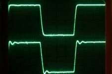
However the DePalma configuration requires another PSU to run the screen which deters me from using it. O.M.O, I don't like complicated o/p stages. The other problem with UL operation which tends to get ignored that the screen is a natural tap on the primary, so it has a poor coupling factor and high leakage inductance relative to it's anode, so it will overshoot and ring with rising frequency. Sectionalised anode and screen windings wound within sectionalised secondary is an exotic luxury makes matters more complicated.
In reality with more modern transformers one has to put a snubber from p-p screen to screen as from screen to anode on each side. Photo shown with and without. The correction is quite perfect.
richj
Most tubes using Int octal sockets are sim. EL34's have g3 on pin 1 which is shield on 6550/KT88's.
From the roost...
I did look at the DePalma schematic which uses UL as sep windings at lower screen voltage and lets the anode rip at 600V. The completely balanced phase splitter idea looks intriguing but is it really necessary ? No (OMO)M; global NFB sorts out any misbalance and I don't like presets other than setting o/p stage bias.
However the DePalma configuration requires another PSU to run the screen which deters me from using it. O.M.O, I don't like complicated o/p stages. The other problem with UL operation which tends to get ignored that the screen is a natural tap on the primary, so it has a poor coupling factor and high leakage inductance relative to it's anode, so it will overshoot and ring with rising frequency. Sectionalised anode and screen windings wound within sectionalised secondary is an exotic luxury makes matters more complicated.
In reality with more modern transformers one has to put a snubber from p-p screen to screen as from screen to anode on each side. Photo shown with and without. The correction is quite perfect.
richj
Attachments
Two (expensive) "off the shelf" transformers exist that are made for this application. The following is cut from the Plitron web site.
The Plitron PAT4140:
Imagine six 6550 power tubes together with this transformer delivering 300 W of output power! With a power bandwidth starting at 14 Hz!. This transformer is intended for powerful bass guitar amplification. As well as superb low frequency response, the frequency range extends up to 88 kHz. The bass guitar sound will be clear, strong and powerful - never "muddy". Secondary impedances of 2 Ohms, 4 Ohms and 8 Ohms offer a wide variety of different series parallel speaker connections. A separate primary 40% ultra linear screen winding is included for special stabilized screen grid power supply applications.
And the PAT4141:
This design is similar to the PAT 4140(above), but only pentode configuration is possible, the secondary impedances are 4 Ohms and 8 Ohms, and the power is 400 W. Primary impedance is 1250 Ohms. Power bandwidth starts at 14 Hz. This will enable eight 6550s, KT88s or equivalent tubes to be used with an anode voltage of 560 Volts. The frequency range extends up to 117 kHz without feedback. This full range transformer provides clear bass guitar sounds like attacks, slaps, etc.
Plitron made some unpotted versions of the 4141 for Marshall, and sold a few of them off on their "surplus" page. I bought two of them, and can tell you that they will do over 400 watts down to 30Hz, but you must keep the bias currents equal. The real upper 3db point is 71 KHz (tested in a tube amp). I plan to use them in a monster HiFi amp. I don't plan to use the usual PPP circuitry.
Yeah, that PAT4140 looks sweet. Just the ticket, but ouch! About twice the cost of the Hammond 1650W! Maybe, just maybe, if my pockets get deep enough. I did read about balancing the bias currents for toroidal output transformers, probably having to use some sort of bias servo. It's starting to be a bit much for my application. I'd like to keep things simple if possible. I think I'd rather give up a bit of power and use UL with screen taps rather than a tetrode connection since I'm trying to design something different, not an SVT clone. Hmm, Maybe Plitron will have another surplus sale...
- Status
- This old topic is closed. If you want to reopen this topic, contact a moderator using the "Report Post" button.
- Home
- Amplifiers
- Tubes / Valves
- Parallel Output Transformers