Hi guys! I am a total newbie to valves and electronics in general, so please be patient with me.....and not too rough. LOL.
I don't think I have ever read a post from SY that I have understood completely.
I have had lots of help from several of you with a speaker build project I recently completed. Thank you all. They are Awesome!
My Thor project
For the last 3 months I have read, read, and read some more, just trying to learn electronics and valve amp / preamp design.
I almost have a handle on some of this stuff.
I would like to build a preamp, and have purchased John Broskie's PCB kit for the ECC802s valves. I am using PSUII software for the power sections. AS recommended in the book "Building Valve Amplifiers" by Morgan Jones I would like to use 12VDC heater supplies. I know it is not neccessary with the Aikido design, but at my level I would prefer to err on the safe and quiet side. DC vs. AC heaters.
I have a question about the HT side that I cannot find an answer to, and would like some help please. The HT voltage to the valves is 1/2ed to aid in noise cancellation, does that mean that the HT should be 2 times the nominal rating of the valve data? I'm guessing no, the circuit will do that for me.
Where I live the voltage seems kinda high at 125VAC as tested over a 4 hour time span with my Fluke 16. I should have tested first, but, being an excited NOOB...., I bought a Hammond 272FX 300-0-300 transformer and 6H 200mA choke from Ebay. With PSUII and the higher than expected mains voltage I end up with ~330V after the transformer. The valves curve suggests something closer to 250V would be better. Will this (power resistor network) be OK?
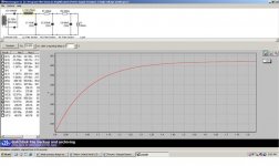
So please check out my PSUII design and let me know what you think I can do to improve it, or if this small ripple will be ok. The Diodes I have purchased are Fairchild Stealth 1200V so I think I'm on the safe side there. I read somewhere that the first cap after the choke should be no larger than ~8uF, and the last cap should not be too large as it may be laggy? Maybe I read too much without understanding what I was looking at..... I'm trying thou.
I don't know how to attach the PSUII screenshot, I think it's too big for the Attach file size? How can I post the screenshot?
Thank you all for your time. Sorry about the lenght of this question. I'm sure I'll have others as I build this preamp.
Renron
I don't think I have ever read a post from SY that I have understood completely.
I have had lots of help from several of you with a speaker build project I recently completed. Thank you all. They are Awesome!
My Thor project
For the last 3 months I have read, read, and read some more, just trying to learn electronics and valve amp / preamp design.
I almost have a handle on some of this stuff.
I would like to build a preamp, and have purchased John Broskie's PCB kit for the ECC802s valves. I am using PSUII software for the power sections. AS recommended in the book "Building Valve Amplifiers" by Morgan Jones I would like to use 12VDC heater supplies. I know it is not neccessary with the Aikido design, but at my level I would prefer to err on the safe and quiet side. DC vs. AC heaters.
I have a question about the HT side that I cannot find an answer to, and would like some help please. The HT voltage to the valves is 1/2ed to aid in noise cancellation, does that mean that the HT should be 2 times the nominal rating of the valve data? I'm guessing no, the circuit will do that for me.
Where I live the voltage seems kinda high at 125VAC as tested over a 4 hour time span with my Fluke 16. I should have tested first, but, being an excited NOOB...., I bought a Hammond 272FX 300-0-300 transformer and 6H 200mA choke from Ebay. With PSUII and the higher than expected mains voltage I end up with ~330V after the transformer.
The valves curve suggests something closer to 250V would be better. Will this (power resistor network) be OK?So please check out my PSUII design and let me know what you think I can do to improve it, or if this small ripple will be ok. The Diodes I have purchased are Fairchild Stealth 1200V so I think I'm on the safe side there. I read somewhere that the first cap after the choke should be no larger than ~8uF, and the last cap should not be too large as it may be laggy? Maybe I read too much without understanding what I was looking at..... I'm trying thou.
I don't know how to attach the PSUII screenshot, I think it's too big for the Attach file size? How can I post the screenshot?
Thank you all for your time. Sorry about the lenght of this question. I'm sure I'll have others as I build this preamp.
Renron
Renron,
First thing - you'll love the Aikido preamp.
A couple of other things (bear in mind that my Aikido PSU is always being tweaked), have you checked what current your tubes will be drawing from the PSU? Broskie has a large table that supplies this information for a given B+ and cathode resistor. You can use current draw from his table to plug into PSUDII, although remember that as you change current-draw, your B+ will change, which in turn will effect your current. However, you could get towards the ballpark with regard to voltage and current-draw. This should give you a little more idea of final B+.
Also, I don't know your tubes, but if your B+ is 330VDC, then each plate in the tubes will see around half that (at least that is my understanding). I found a datasheet for the Telefunken 802s. Most of it was in German, but it does mention 250V, but I think that is likely to be plate voltage, the relatively close 12AU7 has plate voltages of 300V max. You may post the forum asking about that specific tube. If the 250V refers to plate voltage then, that'll be half your B+ voltage, so if you have 330V at your B+, each plate should see 165V.
Your PSU may also suffer from choke ringing. Using a choke input filter, as you are doing, you need to draw a minimum current to ensure that your choke works correctly. In his book, Morgan Jones suggests that B+ / current should give you an idea of minimum choke rating. He says that this is an estimate. Anyway, if you have 330V at B+ and current-draw of 50mA, you'll require a 330/50 = 6.6H choke. In which case, you're close, but check your likely current draw. A better way would be to use a cap input filter, or as I do a "pseudo" cap input filter. Change your LC to a CL(?) filter. You can use the value of the first cap to vary the voltage of B+ AND this negates (maybe not completely) the risk of choke ringing, which is the main problem with Choke-input filters. For example in my PSU (with current of 18mA) I get something like 360V at B+ if I use a 1.5uF cap as cap #1. I actually use a 0.68uF cap and my B+ is around 312VDC. The other problem with my PSU is that I have 10H chokes, which for a choke input filter would require a current of at least 30mA to prevent choke ringing.
Anyway, you may want to rethink your PSU slightly based on your estimated current-draw (you may already have done this and know that it'll be around 50mA). Once you have this figure you should retry your PSU modelling using cap input filters.
If you have problems, I can model some PSU's for you, although I am not expert (my large number of posts are testiment to this). But, it'll have to wait until I am at work and have access to a PC.
Charlie
I am currently running my 6SN7 Aikido at 300V, down from 330V. The sound is pretty much the same, but up at 330V the total dissipation for both sections of my output tubes was at 7.2W, which is quite close to the 7.5W max dissipation for both tubes concurrent. My tubes were going microphonic pretty quickly, and it may have been due to that.
I have a CLCLC filter, with a brand new shunt regulator thrown in the middle to knock down any line variation. It sounds quite smooth.
Next, I am going to try it at 200V with a pure choke-input supply. All I need to do is remove the first 10uF cap. That should tell me if cap-input is adding any switching spikes that are audible.
I don't think I have ever read a post from SY that I have understood completely.
That's OK, I don't think I've ever written one I understood completely...
Anyway, I've done a bit of testing of the Aikido and have found that higher supply voltage (even at the expense of lower standing current to keep the plate dissipation within reason) is a positive for linearity. The last one I built used a pretty conventional CRC raw supply and a simplified Maida regulator; the noise level was very, very low. About 350V, 5mA for each stage (6SN7). The tubes are loafing and the second harmonic distortion cancellation works as advertised.
It's running class A, it's got good PSR, the power supply just isn't nearly as critical as layout and grounding.
Jayme,
How are you calculating your wattage? V x I = W??? If so then:
If I have 312V at B+ and running 7.2mA of current through the plate, I get wattage of 312 x 0.0072 = 2.25W which is 4.6W total for both plates. Working backwards, in order to saturate the wattage requirements at 312V, I would need to be drawing 7.5 / 312 = 24mA total for the tube or 12mA per plate. If this is correct, you must be running your output tubes very hot. I use 470R on my outputs and 1K on my inputs.
In Broskie's table is the quoted cathode current (lk, I presume) for the entire tube or for one plate? I have always assumed that it is for the entire tube.
I would be interested in the performance of your true choke input. The voltage will drop signifcantly as you say and you'll run the risk of ringing your choke, especially as your current will drop as the voltage drops.
It could also be possible that sonically, things may differ. Would the Aikido lose some of its "oomf" with regard to dynamics?
The good thing about the Aikido, is that it allows for experimentation and, as you say, removing a single cap is a five minute job, and that includes clearing space on the workbench, finding the soldering iron, firing it up and having a cup of coffee
Please report back on your findings, either to this thread or a new topic.
Charlie
Whoops. You are right. I was accidentally doubling the dissipation. Silly me...i forgot that each plate only dropped half of the voltage.
SY: As far as operating points, are you saying you recommend higher voltage and lower current (350V @ 5mA) versus lower voltage and higher current (say, 250V @ 10mA)? Or were you just referring to upping the voltage at a given current? I've heard conflicting reviews of what is better, more current or more voltage...
SY: As far as operating points, are you saying you recommend higher voltage and lower current (350V @ 5mA) versus lower voltage and higher current (say, 250V @ 10mA)? Or were you just referring to upping the voltage at a given current? I've heard conflicting reviews of what is better, more current or more voltage...
Sy,
Please could you detail your CRC Maida regulator supply? If you have read my previous posts, you'll know that I am having the dilemma of how to improve my PSU on my Aikido. I could easily settle for 350VDC for my 6SN7's.
My wife has given the green light to build the Aikido into a new chassis. I will be practising making dovetails by hand and building what I hope will be a gorgeous wood chassis with a polished aluminum top-plate. This means that I can put in a new PSU.
Also, Off-topic, but don't you know a thing or two about wine? I just recieved a flyer from Capiaux which is in your area. I have tried their wine once, and liked it. Have you tried their stuff?
Regards,
Charlie
Jayme, Sy, and Cbutterworth,
Thank you for your input, I'm trying to digest and understand your suggestions.
Back to basics; If the Aikido circuit splits the B+ voltage between the 1st and 2nd stage (the input and ouput) valves and the recommended B+ is 250V (from John Broskie's user guide) then won't each valve see 125V?
What am I missing???
specs for the valves are;
Typical characteristic:
Ua = 250 V
Rk = 800 Ù
Ia = 10,5 mA
S = 2,2 mA/V
Ri = 7,7 kÙ
ì = 17
4 valves total = ~42mA Right?
Thanks for the hand holding guys......
What I do not understand is the B+ voltage split thingee.
Ron
Haven't tried Capiaux yet, but I've had other Pinots from some of those vineyards. I'm probably the wrong one to ask- when I see alcohol levels like that in Pinot Noir, I tend to be a bit put off. California Pinot in general tends to be grown in areas where the soil has too much vigor and the climate is too warm. You end up with a big, powerful hot wine, which to me is not what Pinot Noir should be about. There are some few precious exceptions still coming out of Anderson Valley, Mendocino, and selected parts of the Central Coast.
Errr... ummm... OK, back on topic, the Maida I used was identical to the one I used for the screen supply for the Red Light District. I've put that schematic up a few times, so you should be able to find it with a quick search. If not, let me know and I'll repost this weekend when I'm back at my home computer.
Renron, you've got it.
Cbutterworth:
"I will be practising making dovetails by hand and building what I hope will be a gorgeous wood chassis with a polished aluminum top-plate.
sounds like a lot of work and frustration (for me) I'd love to see it's progress when you get started. Ought to be gorgeous!
Ron
"I will be practising making dovetails by hand and building what I hope will be a gorgeous wood chassis with a polished aluminum top-plate.
sounds like a lot of work and frustration (for me) I'd love to see it's progress when you get started. Ought to be gorgeous!
Ron
Renron said:Jayme, Sy, and Cbutterworth,
Thank you for your input, I'm trying to digest and understand your suggestions.
Back to basics; If the Aikido circuit splits the B+ voltage between the 1st and 2nd stage (the input and ouput) valves and the recommended B+ is 250V (from John Broskie's user guide) then won't each valve see 125V?
What am I missing???
specs for the valves are;
Typical characteristic:
Ua = 250 V
Rk = 800 Ù
Ia = 10,5 mA
S = 2,2 mA/V
Ri = 7,7 kÙ
ì = 17
4 valves total = ~42mA Right?
Thanks for the hand holding guys......
What I do not understand is the B+ voltage split thingee.
Ron
Well, the 250V is not "split" between the input and output stages. They both see 250V. The CURRENT is what is split between them.
cbutterworth said:Sy,
Please could you detail your CRC Maida regulator supply? If you have read my previous posts, you'll know that I am having the dilemma of how to improve my PSU on my Aikido. I could easily settle for 350VDC for my 6SN7's.
Regards,
Charlie
Try Voltage Regulator Tubes in a Shunt Regulator mode! I took my CLCLC filter, and added a 500R resistor between the CLC and final LC. Then I added 2 0D3 voltage regulator tubes in series as a shunt to ground right after the resistor. (The 500R was calculated to give 20mA drop across the shunt regulator).
When I pull the gas regulator tubes, it reverts to a simple CLCLC with the equivalent of 500R extra resistance added to the final L DCR.
For 350V PSU, you could use an 0D3 and two 0C3, all in series.
And they glow oh soo cool...
Jayme,
Hmmm.....I always thought that the circuit split the voltage between the plates of the tube, not the current, but when I look back at the schematic, I can never tell quite how this is done. My interpretation is that plate #1 sees 300V, cathode #1 sees 154V, plate #2 150V, cathode #2 4.5V. I always assumed that this meant that each side of the tube sees approximately half of the B+ voltage, which Broskie sets at 300V in his original design.
As for tube regulators, I have pondered over the idea of these, but have always been unsure on exactly how to use them in a PSU to give around 340V. Maybe I'll have to start digging around and see if they would work in my Aikido.
I have a basic web-page with some of my amps shown:
http://homepage.mac.com/butterworthfam/AudioDIY/
Charlie
Thanks Jayme,
Let me see if I got it right this time.
The B+ voltage is seen by each valve,
each valve shares 1/2 B+ at it's plateS,
that's where the noise cancellation takes place.
The current is shared by all valves.
Charlie,
After re-reading your 1st post several times I am begining to understand what you wrote, thank you.
Sy,
Thank you! Even thou you speak in riddles (to a neophite like me) I appreciate your time, experience, wisdom and input. I'll get it eventually. Don't give up on me. This is my first venture into electronics of any sort.
Ron
Let me see if I got it right this time.
The B+ voltage is seen by each valve,
each valve shares 1/2 B+ at it's plateS,
that's where the noise cancellation takes place.
The current is shared by all valves.
Charlie,
After re-reading your 1st post several times I am begining to understand what you wrote, thank you.
Sy,
Thank you! Even thou you speak in riddles (to a neophite like me) I appreciate your time, experience, wisdom and input. I'll get it eventually. Don't give up on me.
This is my first venture into electronics of any sort.Ron
Ron,
You made me think for a second there! I am wondering if Broskie's table list current per plate and not for the entire tube. If this is the case, then I'll have to double my estimate of PSU current draw from around 18mA to 36mA! I'll go back and look at his original schematic and try to calculate current for his set-up and see if it comes out close to his table.
Charlie
Renron said:Yea, Charlie, good post!
It does not seem as clear as it could how each valve "shares" voltage and current.
Thanks,
Ron
Water. Think water. Suppose you have a big pipe with a constant water pressure of 100psi.
Now, take a thinner pipe and attach it to the end. The pressure at the input to that pipe is still 100psi. Measure the flow. Let's say it's 10 gallons per minute (gpm). So since the far end is open, pressure there by definition is zero psi.
OK, take an identical thin pipe and attach it to the big pipe just like its twin. Now you have two pipes whose pressure goes from 100psi at the entrance to zero psi at their exits. But the flow rate doubled!
One more thing to do: let's put the two thin pipes i nseries and attach one end to the big pipe. The pressure runs from 100 psi to zero psi again. But now, the pressure at the end of pipe one and the entrance to pipe two has to be 50psi since the pipes are identical.
Convert "flow" to "current" and "pressure drop" to voltage.
- Status
- This old topic is closed. If you want to reopen this topic, contact a moderator using the "Report Post" button.
- Home
- Amplifiers
- Tubes / Valves
- Valve noobie asks for help / advice