Hum Canceling Scheme?
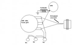
I'm working on my first amplifier build (a Supro clone, parallel single-ended 6v6) and I'm seeking clarification on hum cancelling. I've been told that one scheme is to reference the heater/filament circuit to ground via a 100 ohm pot; better yet to reference it via the "hot" end of the cathode resistor. Does this crude diagram I've made do the trick? Seems simple enough but I'm still new to this stuff....
Many thanks,
Seth
Attachments
I'm not too sure about the hot end thing,
but this is the normal way of doing things,
1. if the heater transformer has a centre tap, earth that.
2. failing that, put a 100 ohm pot across the heater circuit, put the earth on the wiper, listen to the amp, and twiddle the pot until hum is minimised.
does that help.
also, read up on aikido and other noise canceling things at www.tubecad.com, john broskie talks a lot of sense on noise in preamps. you may find that useful.
kind regards
bill
If you make the heater about 30v more positive than the cathode, you can prevent thermionic emission from heater to cathode. Instead of taking the CT to ground, connect a 10uF cap from the CT to ground and arrange two resistors as a voltage divider between B+ and ground, to give you ~30v at the heater. Resistors should be high in value, around 220k - 1Meg. If necessary, to minimise hum still more, you can use a pot instead of the CT.
If you make the heater about 30v more positive than the cathode, you can prevent thermionic emission from heater to cathode. Instead of taking the CT to ground, connect a 10uF cap from the CT to ground and arrange two resistors as a voltage divider between B+ and ground, to give you ~30v at the heater. Resistors should be high in value, around 220k - 1Meg. If necessary, to minimise hum still more, you can use a pot instead of the CT.
Is there any benifit to this if the heater is DC supplied?
Using regulated DC on the heaters worked wonders on my Aikido. Hum is barely audible, whereas before it was quite obvious. While the circuit is relatively simple, I ended-up buying the PSHREG from Welborne labs. It works, although customer support could be better, and some of the parts were substitutes requiring some alteration of PCB mounting. Furthermore, I referenced the center-tap of the 6.3VAC trafo to 1/4 B+ using a cap and voltage divider. It is possible that some of the remaining hum could be due to an slightly off-center center-tap, although I have never measured it.
Going DC on the heaters was the single biggest improvement to my Aikido.
Charlie
Going DC on the heaters was the single biggest improvement to my Aikido.
Charlie
Clarification
Gentlemen:
Thanks much for the replies. A few follow-ups:
1. I considered doing a regulated DC filament supply, but seeing as this is a smallish guitar amp (and a fairly primitive one at that) it seems like overkill. I'll know more once the thing is built (still waiting on the cabinet maker).
2. Ray Moth (or anyone), excuse my inexperience but could you clarify a little more for me? Specifically:
"Instead of taking the CT to ground, connect a 10uF cap from the CT to ground"
-You're still talking about the "fake" CT on the filament circuit, right?
"...and arrange two resistors as a voltage divider between B+ and ground, to give you ~30v at the heater."
-At what point in the B+ supply should I install these? And frankly, I don't know yet how to construct a voltage divider!
3. I understand more or less HOW to do this, but can someone explain WHY? Specifically, from what I can understand, I'm raising the filament voltage relative to ground. Why does this make a difference?
Many thanks,
Seth
Ok...
Remember... votage is a relative difference... THIS point compared to THAT point.
Now, there is a limit, and sometimes a polarity on the voltage you can impose on the heater relative to the cathode of the tube.
Look at tube data sheet and you will see this spec. Let's say the rating is 50 Volts.
If the cathodes of your tubes rested at say 70 Volts... relative to chassis ground, and the heater supply CT was grounded (O volts), then you would be exceeding the 50 Volt difference allowed between heater and cathode.
Tying the heater CT to a 30 Volt source cures this problem... 70 minus 30 equals 40 Volts difference between the anode and the cathode.... problem solved... that's the "why". This is a crude analysis... we have overlooked the fact that cathode voltage has a min and a max. the heater is actually two voltages on two wires. But, you get the idea.
EDIT: this is the most common reason to use a voltage divider for the heater reference. Ray's suggestion is about hotrodding. How it works is the same in either case.
The divider does not require a low DC impedance ( with high divider current, power loss, and heat)... It does require a low AC impedance... that's where the 10uF cap comes in. It provides a low impedance path for AC garbage to ground.
")
Remember... votage is a relative difference... THIS point compared to THAT point.
Now, there is a limit, and sometimes a polarity on the voltage you can impose on the heater relative to the cathode of the tube.
Look at tube data sheet and you will see this spec. Let's say the rating is 50 Volts.
If the cathodes of your tubes rested at say 70 Volts... relative to chassis ground, and the heater supply CT was grounded (O volts), then you would be exceeding the 50 Volt difference allowed between heater and cathode.
Tying the heater CT to a 30 Volt source cures this problem... 70 minus 30 equals 40 Volts difference between the anode and the cathode.... problem solved... that's the "why". This is a crude analysis... we have overlooked the fact that cathode voltage has a min and a max. the heater is actually two voltages on two wires. But, you get the idea.
EDIT: this is the most common reason to use a voltage divider for the heater reference. Ray's suggestion is about hotrodding. How it works is the same in either case.
The divider does not require a low DC impedance ( with high divider current, power loss, and heat)... It does require a low AC impedance... that's where the 10uF cap comes in. It provides a low impedance path for AC garbage to ground.
DC is overkill for this... and many people don't get DC right. Running a tube heater under voltage is one of the worst things you can do.. it destroys tone, lowers output power...
Did you say parallel output tubes? Then how about you simply wire the heaters in reverse... IF the pins are 2 and 7, then hook each end of the secondary to a 2 and a 7 pin. That has the AC out of phase in the heaters in the tubes. When you combine their output, the supply hum is out of phase. That helps. Also, try flipping the connection on your preamp tubes and go with the one with the lowest hum. If the secondary has a center tap, ground it... and if not, do it through balanced resistors or a pot. Make sure your wire is twisted, and use shielded wires for you low level guitar preamp connections...
Did you say parallel output tubes? Then how about you simply wire the heaters in reverse... IF the pins are 2 and 7, then hook each end of the secondary to a 2 and a 7 pin. That has the AC out of phase in the heaters in the tubes. When you combine their output, the supply hum is out of phase. That helps. Also, try flipping the connection on your preamp tubes and go with the one with the lowest hum. If the secondary has a center tap, ground it... and if not, do it through balanced resistors or a pot. Make sure your wire is twisted, and use shielded wires for you low level guitar preamp connections...
Referencing the hum pot wiper to the cathode of output power tubes is an old trick and can work quite well provided that there is also a reasonably large cathode bypass cap as well.. (100uF or more) This works better with tubes having slightly higher cathode bias voltages like the 6L6 or EL34, but depending on operating point the voltage present on the 6V6 cathode ought to be somewhat useful. (Around 10V?) Saves two resistors and a cap, and space. Probably good enough for a guitar amplifier where the filaments are often run with no elevation above ground potential - should quiet down the input stage where it is most likely to be a problem.
Should insufficient cathode voltage be available to do the job you can always resort to the standard divider mentioned in previous posts, that's usually what I do. The opportunity to save a few parts seems worthwhile.
Should insufficient cathode voltage be available to do the job you can always resort to the standard divider mentioned in previous posts, that's usually what I do. The opportunity to save a few parts seems worthwhile.
The voltage divider approach is as follows.
1. Connect a resistor r1 between ground and the physical heater CT or artificial heater CT, whichever you're using.
2. Connect a second resistor r2 between the heater CT and B+. It doesn't matter where in the B+ line you connect it.
3. Connect a 10uF, 100v capacitor from the junction of r1 and r2 to ground.
r1 and r2 form the voltage divider. If we assume that we want the heaters to be biased at about +30v and the value of r1 is 100k, then the value of r2 can be calculated as follows:
r2 = (V-30) * 100k/30
where V is the B+ voltage at the point to which r2 is connected.
For example, if B+ is 300v then r2 should be about 900k to bias the heater at +30V. 910k, which is the nearest preferred value, would do. Of course, if the cathode is already at some positive voltage, then you would aim to bias the heater at the cathode voltage +30v.
Why it makes a difference, as I understand it, is because thermionic emission from the heater element can cause a current to flow between the heater and the cathode and you can get audible hum and noise as a result. Biasing the heater about 30v more positive than the cathode prevents this from happening.
PRNDL said:Hum/noise in a guitar amp is usually related to grounding issues and lead dress.
Not going to agree with you there... most guitar amps use minimal and cheap parts and have super high gain with little or no negative feedback. By the nature of the beast, they have some hum...
It certainly isn't as simple as you make it out to be, such as in an audio amplifier with 1200uf of filter caps and little gain, where you can go.. oops, I botched this ground solder job or whatever.
It takes a disciplined approach, doing every little thing you can to reduce hum in a "smart" way... such as I and others mentioned before.. and much more... it's not just 1 or 2 things...
>> most guitar amps use minimal and cheap parts and have super high gain with little or no negative feedback. By the nature of the beast, they have some hum...
I agree. There's a huge difference between guitar and pro audio.
My comments were addressed to a guitar amp builder who reports that their amp has more him than usual or acceptable.
I don't think recommending DC heaters is appropriate for a guitar amp as the first thing to try. It is, however, very appropriate for an audio amp.
- Status
- This old topic is closed. If you want to reopen this topic, contact a moderator using the "Report Post" button.
- Home
- Amplifiers
- Tubes / Valves
- Hum cancelling scheme?