wiring a tube rectifier PSU
Having settled on a PSU design for my Aikido (basically modifying my current PSU, replacing diodes and main trafo with tube rectification), I am left unsure as to exactly how to wire things up.
PSU's on the Angela Audio site do not use the center-tap of the 5V filament, while the PSU in my Cornet2 does.
Which is best, or does it not really matter?
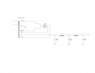
My final design using the center-tap of the 5VCT seondary to give B+ is shown below.
I would appreciate any comments. Note, that I will be using as snubber set-up between switch and trafo.
Charlie
Having settled on a PSU design for my Aikido (basically modifying my current PSU, replacing diodes and main trafo with tube rectification), I am left unsure as to exactly how to wire things up.
PSU's on the Angela Audio site do not use the center-tap of the 5V filament, while the PSU in my Cornet2 does.
Which is best, or does it not really matter?
My final design using the center-tap of the 5VCT seondary to give B+ is shown below.
I would appreciate any comments. Note, that I will be using as snubber set-up between switch and trafo.
Charlie
Attachments
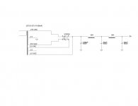
With a directly-heated tube like 5Y3 or 5U4, use the center tap of the heater winding as rectifier output. With an indirectly heated rectifier (5AR4, 5V4), use the cathode pin as the output and ignore the center tap. This will give a small reduction in output ripple and more equal loading of the two halves of the HV transformer.
Tom,
So this is how it would be wired?
I am using a 5V4GT on my Cornet2 and it is wired using the center-tap. The original specs called for 5Y3. Is there any detrimental effect from using the 5V4 here? I certainly notice much better bass definition in the Cornet2 with the 5V4, and I get absolutely no hum whatsoever.
Anyway, if you could give me an idea on whether the PSU in the attachement looks OK, I'd be really grateful. Once I get the transformer, I expect the conversion process from diode rectified to tube rectified to be pretty quick. All I have to swap is the transformer and change wiring of the tube delay tube for a tube rectifier.
Charlie
Attachments
Tom,
I am glad that this forum includes knowledgeable folk like you. I will wire up the PSU as in my second circuit, using the cathode pin (8 as I remember) to take the B+. At present my Aikido PSU is grounded via the PCB (from Broskie), but the center-tap of the 125-0-125 is not grounded at all. It uses a diode bridge. Should it be? Maybe this is the source of some of the quiet hum?
Anyway for my new PSU, should I bus the center-tap to GNDs of the filter as in the following? The PCB has a star-earth, which then goes to chassis earth via 20R lift. I suppose I can experiment a little, as the PSU needs to be earthed to chassis and mains earth somewhere.
Charlie
Attachments
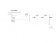
I assume that 20R resistor isn't supposed to be carrying current? So the center tap should go to the filter return and the supply (-) to the PCB. Wiring it as shown will do nicely. You do NOT want the capacitor ripple current flowing in the chassis or in any paths that are common with signal. Although most schematics show the transformer center-tap connected to ground, it is easy to introduce hum that way.
Tom,
The 20R of resistance stands between the PCB GND and chassis GND/Earth. It is wired using a yin-yan diode set-up as shown on Rod Elliot's website - http://sound.westhost.com/earthing.htm. Of course, in my current set-up, the center tap of the transformer is not connected to anything.
Charlie
The 20R of resistance stands between the PCB GND and chassis GND/Earth. It is wired using a yin-yan diode set-up as shown on Rod Elliot's website - http://sound.westhost.com/earthing.htm. Of course, in my current set-up, the center tap of the transformer is not connected to anything.
Charlie
- Status
- This old topic is closed. If you want to reopen this topic, contact a moderator using the "Report Post" button.
- Home
- Amplifiers
- Tubes / Valves
- Wiring a tube rectifier PSU