I got me a minty Scott 233 amp and it looks like it hasn't been switched on in 30 years. Seller said so and for $10 with the matching tuner and both with their rosewood-like cases (Knight speakers, too!), couldn't pass. I have the extension cord rig with the 40 watt bulb ready to go and I'm raring to start her up.
I've done a visual and all looks well, except the 5AR4 tube which has some white frost on the topside. Most tubes appear original, one or two of the smaller ones up front look real old but might be replacements. I popped and re-set each tube.
What should I be looking for at power up and are there any measurements that I should be taking? I do have an amp clamp and several different meters. I've read that one thing to check is the transformer temperatures by touch, but I really don't have a feel for what it should be, so that's not very helpful.
Should I leave it on with the 40 watt bulb arrangement and if so for how long? What next, full power up or move up to a 100 watt bulb?
I do understand that there will be some cap and rectifier replacements in my future, but I'd like to confirm some minimal level of functionality before I dive in and start spending cash.
There is also a loose wire with one end screwed to the chassis. What do I do with the other end?
I'll post some pics soon.
except the 5AR4 tube which has some white frost on the topside.
Boom! It's dead.
As for the dangling wire, you should have, or should immediately install, a three wire power cord. The third wire (green) attaches to the chassis. This is necessary for basic safety, so don't neglect this step.
What are the tube in the scott 233? Can you identify it?
1) Unplug all the tube. At the power transformer, find the center tap of the secandary power supply, there should be 3 cable, 1 connect to pin4 (5AR4), 1 to pin 6(5AR4) and the center tap connect to the ground(or at the negatif of the 1st filter cap) measure the dc resistance from the center tap to pin4 & 5 with DMM. It should be the same or very close. If not, there maybe short circuit.
2)Find the heater pair, if you have 2 type of heater then you may found 2 pair, each pair may be shorted to it self but not to others, so check the short circuit between each terminal. Do the short circuit test for others terminal as well.
If they use 12.6v as heater you might found 3 cable shorted(one is center tap)and not per pair, For heater this is normal , but should not more then 3 terminal.
3) If you're sure that no one have been modified the circuit, u can turn it on and measure the HT, it should be with in the range of the allow power tube plate supply(anode).
Note: Again ground it to the chasis 1st. b4 turn it on
Thanks for replies so far. Is the rectifier tube fried? I'm not clear on the "boom" statement. I can slip this into my next partsexpress order if necessary. I'll get the grounding cord, no problem and I'm looking for the schematic. Pix coming soon.
The seller said it had not been turned on, but he was too young to be the original owner (may have been his parents, though), said he "did not know if it worked." I did notice that one of the heat shields was on an improper tube and that some screws were missing from the bottom access, so someone saw fit to open her up at some point.
Thanks.
>It is not only fried, it's fried in such a way as to guarantee smoke and sparks. Sorry not to be clearer.<
If that is true (that it was fried at some point) are the measurements described above sufficient to establish that the unit is worth salvaging? I'm guessing some of these parts are impossible to get. Don't want to do a bunch of work and find out it was all for nothing.
THANKS!
If that is true (that it was fried at some point) are the measurements described above sufficient to establish that the unit is worth salvaging? I'm guessing some of these parts are impossible to get. Don't want to do a bunch of work and find out it was all for nothing.
THANKS!
DreadPirate said:>It is not only fried, it's fried in such a way as to guarantee smoke and sparks. Sorry not to be clearer.<
If that is true (that it was fried at some point) are the measurements described above sufficient to establish that the unit is worth salvaging? I'm guessing some of these parts are impossible to get. Don't want to do a bunch of work and find out it was all for nothing.
THANKS!
I don't know anything about that unit, and I'm fairly new to this hobby. But, I can say that there is likely nothing in there that can't be replaced with the original, or something close enough - with the help of folks here or on specialty sites for the specific brand/unit. Unless you have to replace transformers, the rest is available at pretty low cost, including good used tubes. The hardest part of making tube stuff is chassis work anyway, and you've got that covered.
Sheldon
DreadPirate said:...I'm looking for the schematic.
Google didn't take long to find this:
http://hhscott.com/pdf/fs/233_299C.JPG
The 7591A is a pretty good sized tube, and should be worth a few watts. For $10, I'd wager this amp is easily worth the trouble to fix it up...
To install a 3 wire ground, remove C212 (the death cap) and R211, replace C211 with an MOV. You could just remove C211, also. The safety ground goes to the chassis. Another problem I see is that the switch and the fuse are on opposite sides. You should ALWAYS switch and fuse the hot. If you fuse/switch the neutral line, current can still flow from the hot to the chassis (because of the safety ground.
sfx1999 said:To install a 3 wire ground, remove C212 (the death cap) and R211, replace C211 with an MOV. You could just remove C211, also. The safety ground goes to the chassis. Another problem I see is that the switch and the fuse are on opposite sides. You should ALWAYS switch and fuse the hot. If you fuse/switch the neutral line, current can still flow from the hot to the chassis (because of the safety ground.
Actually remove both C212 and R211. You can leave C211 in and install a 150Vrms MOV across it if you prefer.
Install a 3 wire line cord.
IIRC most Scott amplifiers use a high voltage ceramic for C212, but in any event it should be removed and if a paper cap was used in this location it must be removed! The resistor should also be removed for the same reason. Note that Scott amplifiers were not designed to use a three wire cord with ground and as a consequence ground loop problems are a real possibility. The usual way around this is a pair of high current (3A) anti-parallel diodes in parallel with something like a 10 ohm >1W resistor. You connect one end of this network to the chassis and the other to the grounding conductor.
The 5AR4 in many Scott amplifiers is located in a spot where it is readily damaged, plus the telefunken 5AR4 often fitted in these amplifiers has a pretty thin glass envelope. I've had lots of Scott amps (299A thru 299D, 296, 99 etc) that had bad rectifier tubes. The amplifier was otherwise fine.
You should plan on replacing D201 and D202 before powering up, in most of these amplifiers it is a selenium rectifier (often half bridge) Pay particular attention to the bias supply filter cap and notice that it is common (can) positive not common negative as is usually the case. If this is bad you have little recourse but to rebuild the can with small axial caps that fit inside the can. The rest are bog standard..
Low level stage filaments all operate in a series string arrangement off of the bias supply for low noise.
The 12AX7A in these amplifiers are usually Telefunkens and last virtually forever. Don't replace any of these unless you are sure they are bad. Replace as a set to assure that the filaments voltage share correctly. (Or check each tube) The 46V filament supply is not a typo it was done deliberately to reduce thermal noise.. (11.5V per tube) Teles run fine at this voltage, some current production ones don't.
This amplifier is well worth the trouble to fix.
kevinkr said:Actually remove both C212 and R211. You can leave C211 in and install a 150Vrms MOV across it if you prefer.
I meant to say that you could have not replaced it with an MOV, and left nothing there. It might not be a bad idea to replace C211 either if you leave it there.
It is very important that you fuse and switch the hot side.
The MOV is for surge protection. Radio Shack has them. You don't really need them, but it is nice to have.
SY said:You'll want to replace those output tubes!
SY is trying to save the forum some of that big moderator salary money by keeping his answers short and to the point.
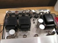
By way of further explanation, the shiny metallic coating on the inside of tubes is typically metallic barium. It is very reactive to atmospheric gasses and is there to scavange up any tiny amounts that leak into the tube over time. If the getter is cloudy, that's a sure sign the tube is grossly leaky and is done for. A nice shiny getter doesn't mean a good tube, as it could fail for other reasons, but it is a necessary condition for a good tube.
Sheldon
Those 7591 are definitely high hour as is evidenced by the very limited amount of getter left in one of those output tubes.
Both JJ (possible quality issues) and Electro-Harmonix make replacement 7591. Stay away from the Sovtek 7591XYZ as these require some modifications to the bias circuitry, and aren't actually 7591 at all - just repinned 6L6 IIRC.
6U8A are quite inexpensive and both of them should be replaced. Sylvania and RCA are both ok. (RCA seem to sound better in some of these amplifiers - again imho.)
This amplifier looks pretty clean otherwise and does not appear to have been stored in a very damp location - all good.
These are very good with old advents incidentally.. (Provided the surrounds aren't rotted out.. ) The first Scott I ever heard was a very healthy 299A with the smaller advents playing Kiss. (My album - I was 19 and a freshman in college.) It made a pretty strong impression, and it marks the beginning of a serious interest in tube audio, (That amplifier was already about 17yrs old at the time and all original.)
Both JJ (possible quality issues) and Electro-Harmonix make replacement 7591. Stay away from the Sovtek 7591XYZ as these require some modifications to the bias circuitry, and aren't actually 7591 at all - just repinned 6L6 IIRC.
6U8A are quite inexpensive and both of them should be replaced. Sylvania and RCA are both ok. (RCA seem to sound better in some of these amplifiers - again imho.)
This amplifier looks pretty clean otherwise and does not appear to have been stored in a very damp location - all good.
These are very good with old advents incidentally.. (Provided the surrounds aren't rotted out.. )
The first Scott I ever heard was a very healthy 299A with the smaller advents playing Kiss. (My album - I was 19 and a freshman in college.) It made a pretty strong impression, and it marks the beginning of a serious interest in tube audio, (That amplifier was already about 17yrs old at the time and all original.)What model tuner did you end up with? I'll keep my fingers crossed and hope you ended up with a 310E - now that would be the tuner to have,, More than likely you have a LT110B or C or comparable 350 series tuner, if so this is quite a wonderful tuner as well. (With a flaky multiplex which once fixed is a pretty impressive performer.) Let me know what you have and I will dig through my notes. I used to service a lot of old tube Scott gear before my business did the titanic routine on me.. 
Scott tuner info from my book written almost two decades ago (Please note this is still copyrighted material) Currently it's available at lulu.com
Don't ignore that tuner!
SCOTT LT-10 MONOPHONIC TUNER (KIT)
An attractive unit usually sold with a golden/brass colored face-plate, with a brown plate trimmed in gold as an option. This tuner features an excellent front end (same as used on the 310 series and all other Scott tuners except the 111 and 350D.) and a three stage IF strip with a ratio detector. Features a multiplex output for use with a stereo adaptor. Features an accurate and attractive transparent illuminated rotary tuning dial on the right side of the face plate, a meter towards the middle and several switches along the lower edge. It features switch selectable AGC levels for best overload margin and stereo reception with the optional external adaptor.
SCOTT LT-110A/B/C STEREOPHONIC TUNERS (KIT)
This model designation covers a huge number of tuners produced over a number of years from the early 1960’s onwards. Very similar in appearance to the LT-10 described above.
The “A” model is considered the most euphonic of the bunch, but in my experience they all sound about the same.... Tube complement is one 6BQ7/6BS8 as a cascode RF amplifier, a 6U8 as a mixer and oscillator, three 6AU6A’s as IF amps/limiter, two 12AU7A’s in the decoder - one as the MPX oscillator, and one as the first audio amplifier, a 6BL8 is used as a wide-band amplifier and 19KHz amplifier, and a 12AT7A is utilized as a stereophonic anode follower audio output amplifier.
The “A” version uses a vacuum tube rectifier and a four tube stereo-adaptor, the “B” version has a solid-state rectifier and a three tube stereo adaptor, with the 12AT7 audio output tube previously mentioned mounted in the area vacated by the rectifier tube, and the “C” version which has an improved limiter circuit using the 6BN6, but which is otherwise similar to the “B” version.
In addition the B/C versions have a feature referred to as: “Sonic Monitor” on the mode switch to tell you when the tuner is receiving stereo. (Basically a tone is generated in this position if the tuner is receiving a stereo signal.) Some “A” versions actually have a neon indicator that lights when stereo is being received- a factory modification I believe, as mine has this feature.
The A/B versions have a flaw in the decoder design that can cause a horrible flanging distortion due to the 38KHz oscillator losing lock in stereo that often is not cured by tube replacement and realignment.... Scott changed a few components in the front end of the decoder to reduce the incidence of this problem. These tuners should be completely re-tubed, aligned and all coupling caps in the audio path replaced with good film caps. These tuners can provide excellent sonic performance when modified, and are also rather attractive looking.
SCOTT LT-111 STEREOPHONIC TUNER (KIT)
A budget model, utilizing a lot of compactron tubes, and a lower cost front-end than the LT-110. Similar styling to the other Scott products of the early 1960’s. Featured rotary tuning. The overall performance of this tuner is nearly as good in all respects as the LT-110 series or the 350 series. Sonically this tuner is can be surprisingly good, particularly if the coupling caps are upgraded. This unit seems to be quite rare, and parts from other models do not interchange with it.
SCOTT LT-314 MONOPHONIC TUNER (KIT)
Topologically speaking this tuner is similar to the LT-10 except that it uses an indicator tube rather than a meter. A good combination with a LM-35 or MPX-335 stereo decoder.
SCOTT 310D MONOPHONIC TUNER
A very interesting tuner, and the predecessor of the justly famed 310E stereo tuner. It has a “Diversity” mode reception feature for broadcast station use, which is basically a bussed muting system to tie together several 310D tuners, and the one with the highest AGC levels dominates the loop. Each unit has a separate antenna and the one with the highest output level mutes all the others. (This also provided redundancy for high reliability receiving applications.) Features higher sensitivity and better capture ratio than the LT-10/LT-314 and comparable models. It Utilizes an additional 6BN6 as a limiter, and a discriminator instead of the ratio detector used in lesser models.
SCOTT 310E STEREOPHONIC TUNER
The finest consumer grade tuner built by Scott. Features the really good RF performance of the 310D with a high quality stereo decoder built in, but it does not have the diversity reception feature of the older tuner. This unit also has relay muting and adjustable stereo/mono switching threshold.
Cosmetically, this tuner has a bright aluminum finish with a brown rotary tuning knob, with a meter in the center and green/blue indicator lamps for stereo and muting. Sonically this tuner is the best of the Scott tuners except for the 4310.
It has a smooth, detailed, almost liquid sound with good extension to both frequency extremes, stereo separation is as good as any tuner I’ve heard. It responds extremely well to modification.
This tuner is loaded with some very unreliable coupling capacitors made by American Radionic, and I recommend replacing all of them - a tedious and time consuming task. I also recommend deleting the series inductors in the final stage of the decoder unless your tape recorder lacks MPX filters. These tuners are considered very desirable. (They are also a nightmare to repair...)
SCOTT 350A/B/C STEREOPHONIC TUNER
See the description of the LT-110 series tuners, as these are the factory versions of the above. Prices slightly higher than the LT-110 series. Overall a pretty cool line of tuners.
SCOTT 350D STEREOPHONIC TUNER
In my opinion this is a tuner that is best avoided in most instances. I thought the sample I listened to sounded no better than some early solid-state units I have heard.
The 350D is a different unit totally redesigned to save money and to embrace new fancier styling. The styling of this unit specifically matches that of the 299D amplifier.
Tube types commonly found in TV’s are widely employed in this model. (6EJ7 for one) None of the tubes used in this design would be considered typical of consumer audio equipment of the day, and consequently finding better sounding tubes for the audio section of the tuner may be difficult.
A linear tuning dial and a tuning tube that indicates signal strength or multipath are key features of the design as is the lack of Scott’s legendary front end assembly.
SCOTT 4310 BROADCAST MONITOR
Less than 1000 of these were ever made, and they are now considered the most desirable Scott tuners available. They feature very different design than any of the other Scott tuners and are difficult to repair. The VU meters on this unit tend to fail with age, in fact of the four I’ve seen two had at least one bad meter, and I get a lot of calls from the field about this particular problem... Sonically, and in every other respect they deserve their magical reputation. They are in the same league as the Marantz 10B and the Fisher FM-1000.
SCOTT LM-35 (FACTORY)/ MPX-335 (KIT) STEREO MULTIPLEX ADAPTOR
One of the few decent stereo adaptors available to the general public, it was basically the same adaptor as that used in the LT-110A/350A in a stand alone, self powered unit. See the description of the decoder as used in the LT-110, all variations present there apply here too.
- Status
- This old topic is closed. If you want to reopen this topic, contact a moderator using the "Report Post" button.
- Home
- Amplifiers
- Tubes / Valves
- Tube Amp Startup