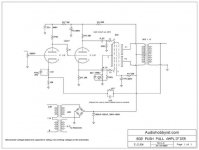
So I built myself the amp in the attached schematic and had a question about the feedback part of the amp. I am using Hammond 1609 output transformers and the required 200 volts B+.
In the feedback path Is there an equation or rule of thumb for choosing the resistor and cap in relation to the impedance of the transformer? I was thinking of just putting in a 10k pot in place of the resistor and seeing how it sounds. What purpose does the 1200pf cap serve?
Thanks for helping a beginner!
Attachments
choice of feedback resistor and capacitor
Pyre :
The impedance of the transformer does not really enter into it. The note on the drawing that says pick C based on the transformer is not about transformer impedance.
The overall gain of the amplifier will be approximately equal to the feedback resistor value divided by the cathode resistor it connects to, or in this case about 47. So you select the feedback resistor based on the overall gain you want. (some people will rephrase that and say you pick it based on the amount of feedback you want to apply, same thing but said the opposite way )
The capacitor is there to reduce the gain at high frequencies to prevent oscillations. The impedance of the R and C combination will be lower, so the gain will be lower. ( The feed back is greater ).
The reason the note in the drawing says to pick C based on the transformer used is that the transformer will have a peak in its frequency response at maybe 50KHz for example, which could cause positive feedback and oscillation.
The simplest way of picking a value of C is to build the circuit and test it with a scope and signal generator with various values of C in place, and with various loads on the output, and pick the C that works best.
Thanks!
That makes sence. I guess if I am going to build amps for fun I should buy a scope and learn how to use it. I have looked at them before but have not know which one to buy. I see Sayal has a handheld portable on on sale for 130$ or something.
I am going to fire up the new amp this weekend. I have to pick up the transformers on Saturday. So for now I will just have to go with the 4k7 and hope for the best.
Where is Stittsville? I have not lived in Ontario very long and do not know where all the towns are yet.
Pyre said:So I built myself the amp in the attached schematic and had a question about the feedback part of the amp. I am using Hammond 1609 output transformers and the required 200 volts B+.
In the feedback path Is there an equation or rule of thumb for choosing the resistor and cap in relation to the impedance of the transformer?
Not really. There are equations that'll tell you what your Avcl will be and all that. However, these don't tell you how it sounds in the end. FWIW:
VT Designs: Don't require large amounts of gNFB, and can't tolerate it either. Excessive gNFB will make it sound very "solid statey", and not good solid state either. About the best way to describe this effect would be to compare it to trying to listen with a heavy blanket or comforter thrown over the speeks.
MOSFET Designs: Can tolerate a bit more gNFB, but the "Big Box" implementations use way too much, and sound like it.
BJT Designs: These like lots of gNFB, and require it in order to sound good. That's why these usually incorporate a very high gain interstage (called a "VAS") with active loading or bootstrapping to maximize the open loop gain.
In general, the more gNFB you add, the more the sound stage contracts. It's a design trade-off. For a pentode based design like that, getting rid of that pentode nastiness might be more important than a wide open sound stage.
I was thinking of just putting in a 10k pot in place of the resistor and seeing how it sounds. What purpose does the 1200pf cap serve?
Thanks for helping a beginner!
Definitely do that to see what sounds best. Might even be a good idea to leave the pot in the circuit and adjust to taste based on what kind of music you're listening to. The last design I did, I played around with varying amounts of gNFB to see what sounded best.
I would also suggest listening with no gNFB applied at all for at least a week with different program material. That way, you can determine what sonic defects there are that need fixing.
Where is Stittsville?
Stittsville is on the western edge of Ottawa, and technically a part of it.
We used to be a seperate entity with our own mayor and councillors but a few years ago the provincial government decided it didnt like having to deal with so many troublesome politically independant municipalities, so it started merging every town and village into "super cities". Fewer cities , fewer mayors, fewer problems ...
Sorry, political rant mode now off.
Now back to tubes and stuff :
Might even be a good idea to leave the pot in the circuit and adjust to taste based on what kind of music you're listening to.
Some manufacturers, and I am thinking particulary of an article I have around somewhere about some Bogen amps, did this in amps. Part of the idea I believe was to get the setting that best matched your particular speakers.
- Status
- This old topic is closed. If you want to reopen this topic, contact a moderator using the "Report Post" button.