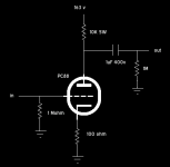
hi I designed a simple SE triode preamplifier that can be seen in the picture. the preamp plays nicely and there is a vast ammount of bass compared on my previous preamp but I need a little bit of help on how can I bias it into class-A operation. I know what I have to do to bias it but I do not know the values of the components.
Should the mA at the anode be the maximum allowed by the tube datasheet?
This tube draws about 12.5mA at max and I only can make it draw 8.2mA, so this is not class-A right?
I need some info please.
cheers!
Should the mA at the anode be the maximum allowed by the tube datasheet?
This tube draws about 12.5mA at max and I only can make it draw 8.2mA, so this is not class-A right?
I need some info please.
cheers!
Attachments
No, it is operating in class A for the amplitude levels you require otherwise distortion would be severe. (Other classes of operation imply conduction over less than 360 degrees.)
The component values you have chosen look reasonable for the tube type and voltages you have chosen.
To increase plate current reduce the cathode resistor value, note that as current increases the plate voltage will drop which will have the effect of reducing the change in plate current that you would expect from a reduction in cathode resistor value. Values between 47 and 100 ohms are reasonable, try a couple of values in this range and determine which you like best. For lowest output impedance a high quality bypass cap is recommended (given the several hundred uF required it should be made up of several good caps in parallel.) Alternately you could use something like 3 red leds in series in place of the cathode resistor.
I used a 470mf bypass cap in order to extend a bit the range in the bass section. The leds idea is great indeed.
Also I have adapted a pontentiometer as cathode resistor and I change values easily. Although I have never reached more then 8.2mA at the anode even if I set the cathode resistor in small or large values... Maby this means that the tube is highly used? I do not know...
The sound is very acceptable though...
I was wondering of how could I push the tube to its limits to achieve a classA device but as you say it has to operate in classA even if the plate current is much lower...?
Thank you very much!!
This is a class A circuit. The grid resistors should probably be made smaller - on the input and next stage as shown in your pic. 1M is maximum permissible according to tube sheet. While they allow smaller bypass caps, I think a circuit sounds better with lower value grid resistors. If you drive the tube hard - a high value here can actually change the bias voltage causing you to lose linearity. Try 220k, 330k and check your plate current and sound again.
If you aren't using a negative feedback loop, im not sure 100 ohms in the cathode is enough negative feedback to keep distortion down. You say this sounds OK?
If you aren't using a negative feedback loop, im not sure 100 ohms in the cathode is enough negative feedback to keep distortion down. You say this sounds OK?
Ok to be honest this is my second successfull attempt to design a preamplifier from scratch using an RF tube.
I thought so about the grid resistors, It seemed too big to me too...
The strange thing to my point is that yes, the preamplifier sound good to almost any value of cathode resistor with only small changes mainly in the bass section.
What value would you propose for the cathode? smaller or greater? the datasheed sayr recommended 100ohms that is why I chosed so.
The high range transparency is very good when I change the MKT output cap with a wima MKP and I guess it will be nicer with more expensive caps.
I think the greater the value of this cap the more extend in low frequencies?
For the input cap I choosed to use the output cap of the previous stage (the one inside a cd player, etc) and I prefered not to add another passive component there...
Finaly I believe a second identical stage will boost up the total gain, but what the value of the capacitor between two stages can be? The same as the output cap or smaller?
Wour help is very important to me as I am newbie in designing, and I can say I enjoy it!
Thank you so much for the info!
Cycline3 said:This is a class A circuit. The grid resistors should probably be made smaller - on the input and next stage as shown in your pic. 1M is maximum permissible according to tube sheet. While they allow smaller bypass caps, I think a circuit sounds better with lower value grid resistors. If you drive the tube hard - a high value here can actually change the bias voltage causing you to lose linearity. Try 220k, 330k and check your plate current and sound again.
If you aren't using a negative feedback loop, im not sure 100 ohms in the cathode is enough negative feedback to keep distortion down. You say this sounds OK?
A good ECC88/PC88 without local feedback should still be capable of rather respectable thd% at a couple of Vrms. See Morgan Jones for more on this. FWIW I no longer use any feedback, local or otherwise in most of my designs and achieve linearity everywhere except an SE output stage that would be considered more than acceptable even by SS design standards. SY will probably back me up on this one..
neazoi said:Ok to be honest this is my second successfull attempt to design a preamplifier from scratch using an RF tube.
I thought so about the grid resistors, It seemed too big to me too...
The strange thing to my point is that yes, the preamplifier sound good to almost any value of cathode resistor with only small changes mainly in the bass section.
What value would you propose for the cathode? smaller or greater? the datasheed sayr recommended 100ohms that is why I chosed so.
The high range transparency is very good when I change the MKT output cap with a wima MKP and I guess it will be nicer with more expensive caps.
I think the greater the value of this cap the more extend in low frequencies?
For the input cap I choosed to use the output cap of the previous stage (the one inside a cd player, etc) and I prefered not to add another passive component there...
Finaly I believe a second identical stage will boost up the total gain, but what the value of the capacitor between two stages can be? The same as the output cap or smaller?
Wour help is very important to me as I am newbie in designing, and I can say I enjoy it!
Thank you so much for the info!
Why do you need more gain? If you really do, choose a tube with a higher mu like the 5842, Russian 6S4P-EV (both 40 - 50) or D3A (70) triode connected. Minimizing the number of stages is always good for transparency. I'm very minimalist in audio path design, and rather the reverse in psu design.


kevinkr said:A good ECC88/PC88 without local feedback should still be capable of rather respectable thd% at a couple of Vrms. See Morgan Jones for more on this. FWIW I no longer use any feedback, local or otherwise in most of my designs and achieve linearity everywhere except an SE output stage that would be considered more than acceptable even by SS design standards. SY will probably back me up on this one..
OK sounds great.. have an schematics of what you mean? Even a generalized one? Just to show how you are laying out a stage? Cause it sounds like you mean running full tilt on gain, no FB from cathode resistor, no global feedback and from reading and experience, that usually is not a good combo for hi fidelity. But I'm open to the idea for sure - and interested to see what you mean. Thanks, -Sean
neazoi said:I thought so about the grid resistors, It seemed too big to me too...
What value would you propose for the cathode? smaller or greater? the datasheed sayr recommended 100ohms that is why I chosed so.
I think the greater the value of this cap the more extend in low frequencies?
For the input cap I choosed to use the output cap of the previous stage (the one inside a cd player, etc) and I prefered not to add another passive component there...
Finaly I believe a second identical stage will boost up the total gain, but what the value of the capacitor between two stages can be? The same as the output cap or smaller?
First and foremost this is a general explanation to your questions.
I would drop the grid resistors for linearity and lower noise. As for the cathode R, there isn't a hard and fast rule - it depends on the circuit and the voltage of your power supply. When you choose plate and cathode Rs, you are defining the operating voltage of the plate, the bias voltage on the tube and the current going through it. A safe and typical design is to run the tube at about 60% of it's plate dissipation. In this case just under 1watt (I believe this is a 1.8 watt tube). So you choose your plate and cathode resistors so that you have that .95 watt dissipation, and the voltage on the plate is say 60% of B+ so you have lots of headroom to swing AC voltage (your music signal) without distortion. Make sense? So you choose resistors that make this happen - it's not a rule where you always use 100ohms. MAke sense?
Cycline3 said:
OK sounds great.. have an schematics of what you mean? Even a generalized one? Just to show how you are laying out a stage? Cause it sounds like you mean running full tilt on gain, no FB from cathode resistor, no global feedback and from reading and experience, that usually is not a good combo for hi fidelity. But I'm open to the idea for sure - and interested to see what you mean. Thanks, -Sean
The key is I choose tubes with the appropriate mu for the application I am going to use them in. Global feedback is not required in most applications, except arguably in a power amplifier where it provides reduced output impedance and lower distortion, but you can design for better linearity in the first place, and if you can design a speaker system to work with source impedances typical of SE amplifiers then you don't even need the global feedback.
Take a look at my website and look for the dht transformer coupled linestage. (Its also on the positive feedback online website.)
I would drop the grid resistors for linearity and lower noise. As for the cathode R, there isn't a hard and fast rule - it depends on the circuit and the voltage of your power supply. When you choose plate and cathode Rs, you are defining the operating voltage of the plate, the bias voltage on the tube and the current going through it. A safe and typical design is to run the tube at about 60% of it's plate dissipation. In this case just under 1watt (I believe this is a 1.8 watt tube). So you choose your plate and cathode resistors so that you have that .95 watt dissipation, and the voltage on the plate is say 60% of B+ so you have lots of headroom to swing AC voltage (your music signal) without distortion. Make sense? So you choose resistors that make this happen - it's not a rule where you always use 100ohms. MAke sense?
The tube has a dissipation of 2W max.
I made the cathode R to 80 Ohm. The voltage drop across it is 0.65v.
So the current running through it is (0.65/80)*1000=8.125mA
With the same calculating method the current on the plate for 11kohm R is (95/11000)*1000=8.636mA
They are very close together as would expected.
Now the tube has 2W dissipation as I said. As you suggest, 60% is 1.2W.
The plate voltage is 163v. From P=V*I we have that (1.2/163)*1000=7.361mA
Which is a bit lower than 8.636mA but still close so I am running the tube a bit hotter but in safe area.
Also my +B is 250v and the plate voltage is 163v. That is (60*250)/100=150v
This confirms that I have run the tube a bit harder)))))
I would like no know two things in this post please..
Q1: I am wondering if my calculations are right (the way I do them)?
Q2: Even if you run a tube at 60% plate dissipation it still can be class-A. These two are independent right?
I greatly appreciate your help!
Best regards!
The tube has a dissipation of 2W max.
I made the cathode R to 80 Ohm. The voltage drop across it is 0.65v.
So the current running through it is (0.65/80)*1000=8.125mA
With the same calculating method the current on the plate for 11kohm R is (95/11000)*1000=8.636mA
They are very close together as would expected.
Now the tube has 2W dissipation as I said. As you suggest, 60% is 1.2W.
The plate voltage is 163v. From P=V*I we have that (1.2/163)*1000=7.361mA
Which is a bit lower than 8.636mA but still close so I am running the tube a bit hotter but in safe area.
Also my +B is 250v and the plate voltage is 163v. That is (60*250)/100=150v
This confirms that I have run the tube a bit harder
)))))I would like no know two things in this post please..
Q1: I am wondering if my calculations are right (the way I do them)?
Q2: Even if you run a tube at 60% plate dissipation it still can be class-A. These two are independent right?
I greatly appreciate your help!
Best regards!
neazoi said:The tube has a dissipation of 2W max.
I made the cathode R to 80 Ohm. The voltage drop across it is 0.65v.
So the current running through it is (0.65/80)*1000=8.125mA
With the same calculating method the current on the plate for 11kohm R is (95/11000)*1000=8.636mA
They are very close together as would expected.
Now the tube has 2W dissipation as I said. As you suggest, 60% is 1.2W.
The plate voltage is 163v. From P=V*I we have that (1.2/163)*1000=7.361mA
Which is a bit lower than 8.636mA but still close so I am running the tube a bit hotter but in safe area.
Also my +B is 250v and the plate voltage is 163v. That is (60*250)/100=150v
This confirms that I have run the tube a bit harder
Q1: I am wondering if my calculations are right (the way I do them)?
Q2: Even if you run a tube at 60% plate dissipation it still can be class-A. These two are independent right?
OK Again this is IN GENERAL. In a simple circuit under *ideal* conditions, there is no grid current so the current through your cathode R, the tube and the plate R is all the same. Think of it as a straight pipe. If you are getting some variances, it could simply just be fluctuations in V in the power supply, your meter... whatever.
As to the 2W rating - check your tube - the sheets I looked at were 1.8. Either way, 1.2 watts is within rating and won't hurt anything. Your calculations look ok at quick glance.
Now, let's try to clarify this - dissipation. For a simple voltage amp - there is no need to run the tube this hard. You aren't generating power into anything... However, tubes are generally more linear (and sound better) running at higher currents. Look at the data sheets. The curves are straighter as the current goes up.
Therefore, people try to find a balance between running a tube hard and tube life (how long it will last). Thus the 60% or so guideline.
Now class of operation has nothing to do with dissipation. It refers to how much of the music signal the tube carries. IN the case of a single tube voltage amplifier you have here - the entire music signal is going through it - what was said earlier - the full 360 degrees. That is class A - the tube carries ALL of the signal. Class B is when the tube only carries part of the signal - in the case of an output circuit with tube tubes - imagine each tube amplifies half the signal. Then you put the 2 halves back together to have the whole signal again (in the transformer). That's class B - where the tube carries less than the full 360 audio signal. AB is a function in between where the amp works class A at low power and class B at high power - but that's not an issue here with your circuit. Running anything other than class A here would create major distortion and you couldn't listen to it.
Help?
kevinkr said:The key is I choose tubes with the appropriate mu for the application I am going to use them in. Global feedback is not required in most applications, except arguably in a power amplifier where it provides reduced output impedance and lower distortion, but you can design for better linearity in the first place, and if you can design a speaker system to work with source impedances typical of SE amplifiers then you don't even need the global feedback. Take a look at my website and look for the dht transformer coupled linestage. (Its also on the positive feedback online website.)
Kevin, got to admit that seems very intriguing. It seems more or less that that line stage is running like a typical output stage would. Im not sure I want to throw another transformer in the mix, but this is definitely something I'm going to have to play with and look at more. Thanks.
Cycline3 said:
<snip> Im not sure I want to throw another transformer in the mix, but this is definitely something I'm going to have to play with and look at more. Thanks.
Exactly what I thought until I tried it, originally this was just an experiment to see how it would work out. Since then it has become my one and only line stage and has elvolved into what you read about..
- Status
- This old topic is closed. If you want to reopen this topic, contact a moderator using the "Report Post" button.
- Home
- Amplifiers
- Tubes / Valves
- design help needed.